Electrostatically Atomizing Device

a technology of atomizing device and atomizing chamber, which is applied in the direction of corona discharge, combustion types, instruments, etc., can solve the problem of not being applicable to an appliance such as a hair dryer

Active Publication Date: 2009-01-01
MATSUSHITA ELECTRIC WORKS LTD
View PDF9 Cites 51 Cited by
  • Summary
  • Abstract
  • Description
  • Claims
  • Application Information

AI Technical Summary

Benefits of technology

[0017]Further, it is equally possible to provide a plurality of the opposed electrodes in correspondence to the emitter electrode. In this instance, each of the opposed electrodes is spaced by the same distance to each associated one of the emitter electrodes so as to give the same electric field strength to the discharge end of each emitter electrode, assuring to generate a large amount of the mist in a stable manner.

Problems solved by technology

However, this scheme will take at least several minutes to obtain the water (condensed water) generated at the heat exchanger and supply the condensed water to the emitter electrode, and therefore poses a problem of being not applicable to an appliance such as a hair dryer which is operated only for a short time.

Method used


Image

  • Electrostatically Atomizing Device
  • Electrostatically Atomizing Device
  • Electrostatically Atomizing Device

Examples


1st embodiment

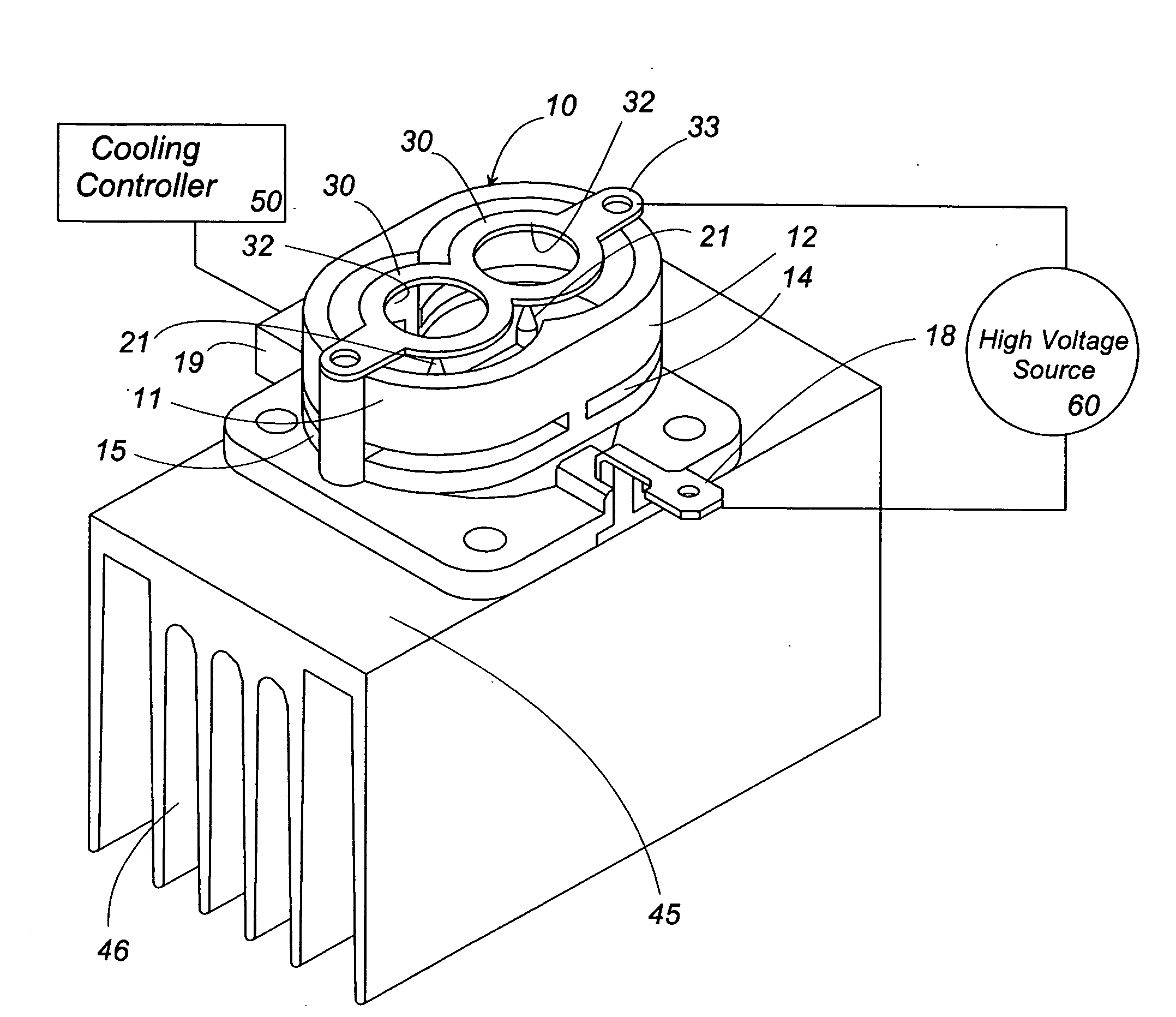
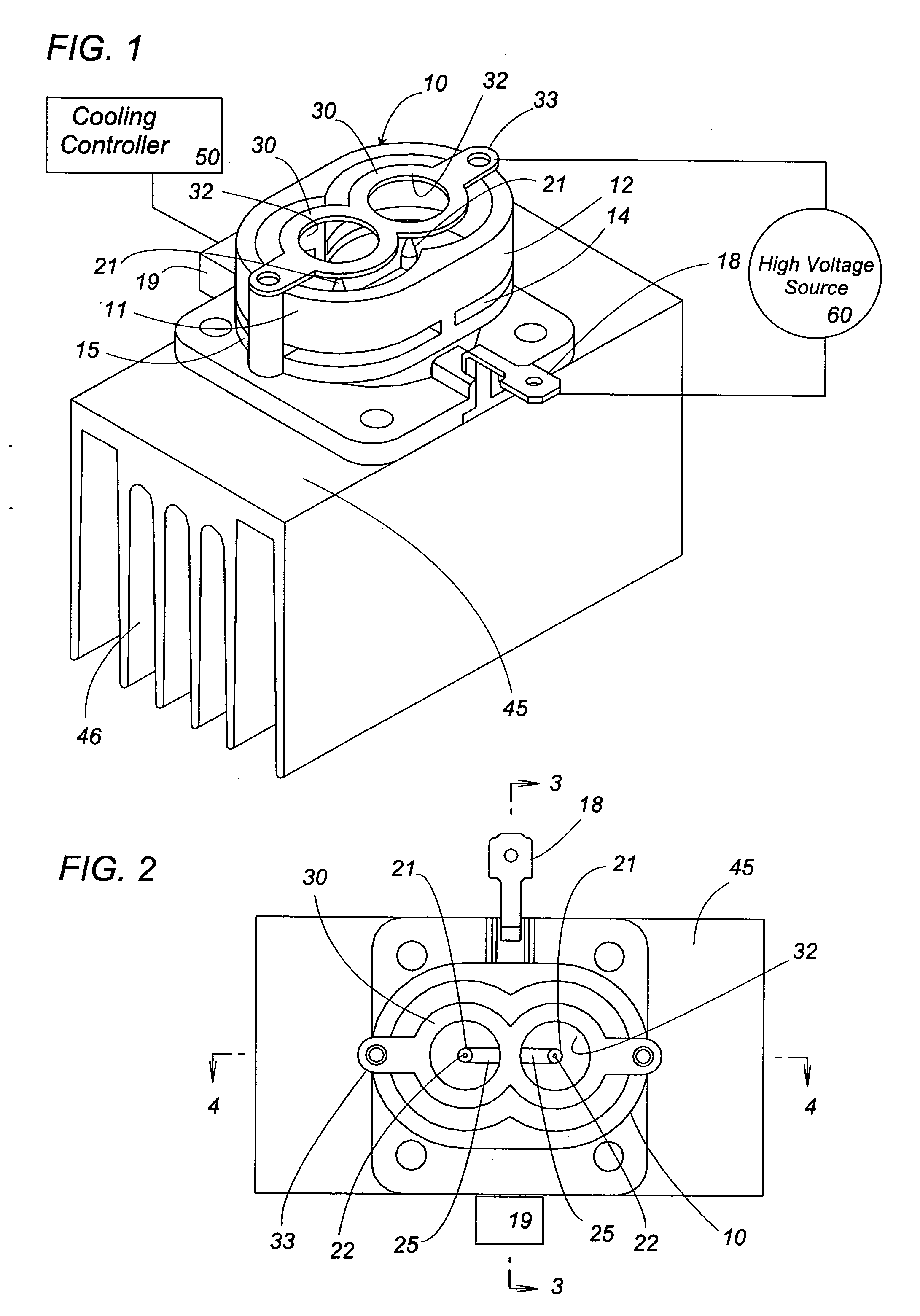
[0028]An electrostatically atomizing device in accordance with the first embodiment of the present invention is explained with reference to the attached drawings. As shown in FIGS. 1 to 4, the electrostatically atomizing device includes a casing 10 in which a plurality of emitter electrodes 21 are disposed. Attached to the top opening of the casing 10 is an electrode plate integrating a plurality of opposed electrodes 30 which are opposed respectively to the ends of the emitter electrodes 21 by a predetermined distance. The electrode plate is formed with a plurality of circular openings 32 each having a center axis on which the tip of each corresponding emitter electrode 21 is disposed.

[0029]The emitter electrode 21 is coupled to a refrigerator 40 which cools and condenses the water contained in the ambient air on the emitter electrode 21. The emitter electrode 21 and the opposed electrode are connected to a high voltage source 60. The high voltage source is provided to apply a pred...

2nd embodiment

[0039]FIG. 8 illustrates an electrostatically atomizing device in accordance with the second embodiment of the present invention which is basically identical to the above embodiment except that a fan 110 is accommodated within a single housing 100 together with the casing 10. The casing 10, which carries the emitter electrode 21, the opposed electrode 30, the Peltier module 40, and the heat radiating fins 46, is disposed in the upper end of the housing 100, while the fan 110 is disposed in the lower end of the housing 100. In the present embodiment, the Peltier module is utilized as a heat exchanger defining a refrigerator at its one end, and a heat radiator at the other end. The fan 110 is provided to take in the ambient air through the air inlet 102 and discharge it outwardly through an air intake path 104 and a heat exchange path 106 formed in the housing 106. The air intake path 104 is formed downstream of the fan 110 between the casing 10 and the housing 100 to guide the forced...


PUM


Abstract

The present invention provides an electrostatically atomizing device capable of instantly giving an electrostatically atomizing effect without requiring a water tank. The electrostatically atomizing device includes an emitter electrode, an opposed electrode opposed to the emitter electrode, a water feeder configured to give water on the emitter electrode, and a high voltage source configured to apply a high voltage across said emitter electrode and said opposed electrode to electrostatically charge the water on the emitter electrode for spraying charged minute water particles from a discharge end of the emitter electrode. The water feeder is configured to condense the water on the emitter electrode from within the surrounding air, enabling to supply the water on the emitter electrode in a short time without relying upon an additional water tank. Thus, an atomization of the charged minute water particles can be obtained immediately upon use of the device.

Description

TECHNICAL FIELD[0001]The present invention relates to an electrostatically atomizing device, and more particularly to the electrostatically atomizing device which condenses water contained in the air and electrostatically charge the condensed water so as to spray the minute water particles of a nanometer order.BACKGROUND ART[0002]Japanese patent publication No. 5-345156 A discloses a prior art electrostatically atomizing device generating charged minute water particles of a nanometer order (nanometer sized mist). The device is configured to apply a high voltage across an emitter electrode supplied with the water and an opposed electrode to induce Rayleigh disintegration of the water carried on the emitter electrode, thereby atomizing the water. The charged minute water particles thus obtained contain radicals and remain over a long period of time to be diffused into a space in a large amount, thereby being allowed to react effectively with offensive odors adhered to a room wall, clo...

Claims


Application Information

Patent Timeline
Patent Type & Authority Applications(United States)
IPC IPC(8): B05B5/057B05B5/08B05B5/025B05B5/053
CPCB05B5/0255B05B5/057B05B5/0533
Inventor IMAHORI, OSAMUHIRAI, TOSHIHISAHIRAI, KISHIKOSUGAWA, AKIHIDEMIHARA, FUMIOAKISADA, SHOUSUKEWATANABE, TOMOHARUYOSHIOKA, HIROKAZUKOBAYASHI, KENTAROMURASE, SHINYAHIRAI, KOUICHIIMAI, JUNJI
Owner MATSUSHITA ELECTRIC WORKS LTD
Why Eureka
Try Eureka