
Commutation of an electromagnetic propulsion and guidance system

a technology of electromagnetic propulsion and guidance system, which is applied in the direction of electronic commutators, motor/generator/converter stoppers, dynamo-electric converter control, etc., can solve the problems of limited processing apparatus, limited number of active components of conventional robots, and limited freedom of conventional robots

Active Publication Date: 2009-01-01
BOOKS AUTOMATION US LLC
View PDF99 Cites 12 Cited by
  • Summary
  • Abstract
  • Description
  • Claims
  • Application Information

AI Technical Summary

Benefits of technology

[0007]In yet a further embodiment, a substrate processing apparatus has a controller for commutating a motor including circuitry for calculating an adjustment electrical angle, and an amplifier operable to utilize the adjustment electrical angle in a common set of commutation equations so that the common set of commutation equations is capable of producing both one and two dimensional forces in the motor.

Problems solved by technology

As can be realized, throughput of the processing apparatus is limited by the handling rate of the transport apparatus.
In addition, a conventional robot requires a considerable number of active components, including joints, arms, motors, encoders, etc.
A conventional robot generally has a limited number of degrees of freedom, and providing power and control for the robot generally requires breeching the envelope of the transport chamber.

Method used


Image

  • Commutation of an electromagnetic propulsion and guidance system
  • Commutation of an electromagnetic propulsion and guidance system
  • Commutation of an electromagnetic propulsion and guidance system

Examples


Embodiment Construction

[0003]The disclosed embodiments are directed to a method of commutating a motor including calculating an adjustment electrical angle, and utilizing the adjustment electrical angle in a common set of commutation equations so that the common set of commutation equations is capable of producing both one and two dimensional forces in the motor.

[0004]In another embodiment, a method of commutating a motor includes calculating an adjustment electrical angle, and entering the adjustment electrical angle into commutation equations for commutating motor windings to produce forces in the motor in at least one dimension, wherein the adjustment electrical angle is determined so that commutation equations for producing forces in the motor in but one of the at least one dimension are common with commutation equations for simultaneously producing forces in the motor in two of the at least one dimension.

[0005]In another embodiment, an apparatus for commutating a motor includes circuitry for calculat...


PUM


Abstract

A method of commutating a motor includes calculating an adjustment electrical angle, and utilizing the adjustment electrical angle in a common set of commutation equations so that the common set of commutation equations is capable of producing both one and two dimensional forces in the motor.

Description

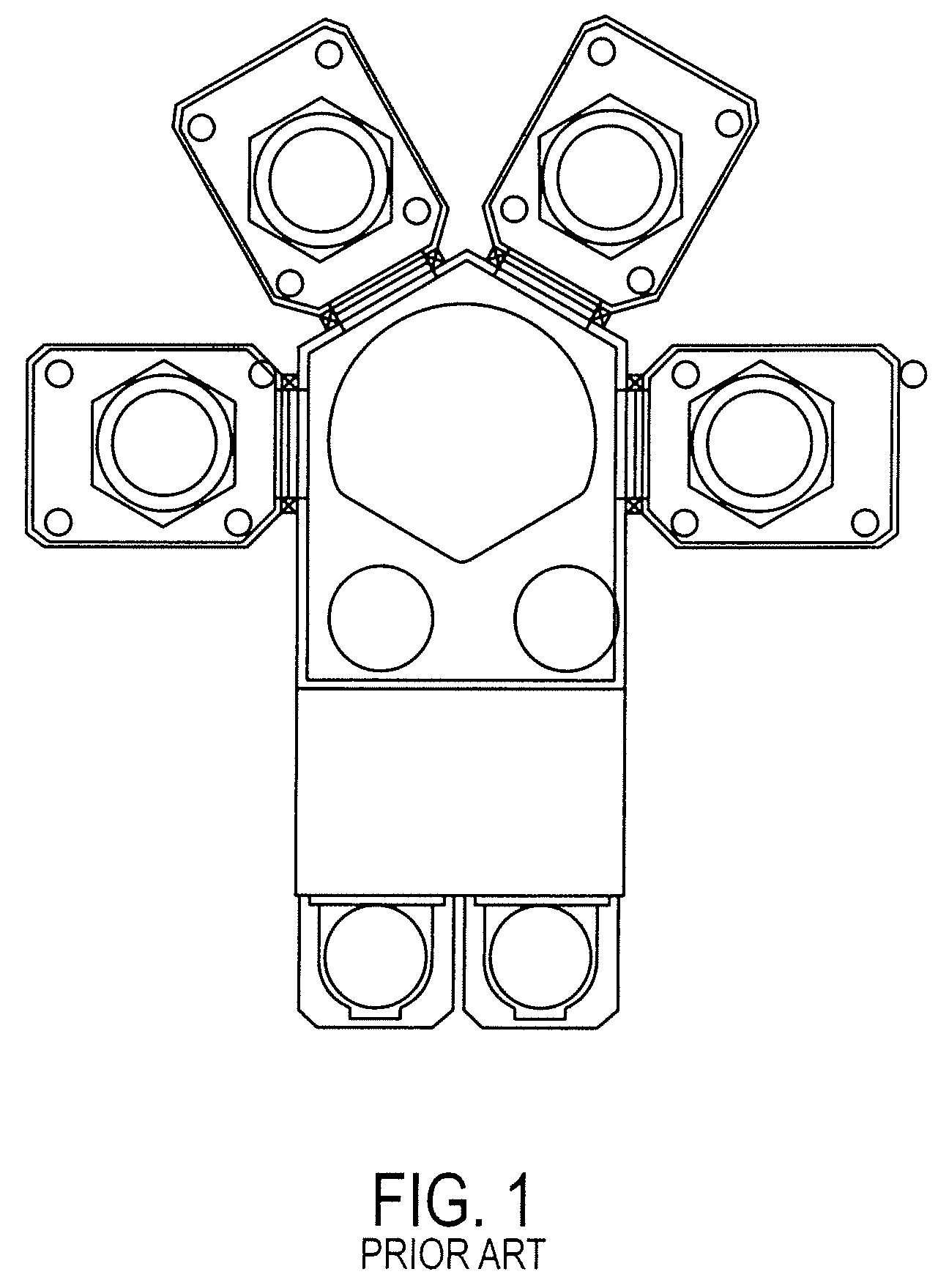
BACKGROUND[0001]The embodiments described herein relate to a method and system for commutation of an electromagnetic propulsion and guidance drive, in particular for a magnetically levitated material transport platform.BRIEF DESCRIPTION OF RELATED DEVELOPMENTS[0002]A schematic plan view of a conventional substrate processing apparatus is shown in FIG. 1. As can been seen, the processing modules of the apparatus in FIG. 1 are placed radially around the transport chamber of the processing apparatus. A transport apparatus, which may be a conventional two or three axis of movement apparatus, for example, a robot, is centrally located in the transport chamber to transport substrates between processing modules. As can be realized, throughput of the processing apparatus is limited by the handling rate of the transport apparatus. In addition, a conventional robot requires a considerable number of active components, including joints, arms, motors, encoders, etc. A conventional robot generall...

Claims


Application Information

Patent Timeline
IPC IPC(8): H02P31/00
CPCF16C32/0493F16C41/008H02P2209/07H02P6/142H02P6/15F16C2380/26
Inventor HOSEK, MARTINMOURA, JAIRO TERRAHOFMEISTER, CHRISTOPHER
Owner BOOKS AUTOMATION US LLC
Learn More