Electrical Testing System

a testing system and electrical technology, applied in the direction of printed circuit testing, measurement devices, instruments, etc., can solve the problems that the original electrical test method used on the ssb cannot be reproduced on the dsb, and cannot be satisfactorily performed

Inactive Publication Date: 2009-01-01
KINSUS INTERCONNECT TECH
View PDF7 Cites 5 Cited by
  • Summary
  • Abstract
  • Description
  • Claims
  • Application Information

AI Technical Summary

Benefits of technology

[0010]According to the objective, the solution of the present invention is to provide an electrical testing system to perform inspection on the DSB (as there are terminals which are electrically connected with each other on each of the two sides, respectively). The system includes a test board for forming electrical contact with the PCB, a test fixture for supporting the test board and the PCB, a plurality of testing probes for outputting the electrical signal, and a sensor for receiving the electrical signal through the PCB and the test board. When the PCB is mounted on the test board, the electrical signals are correspondingly outputted from the testing probes in sequence, and are transmitted to the PCB through the test board, and based upon whether the electrical signal is received by the sensor to thereby determine whether the terminals on the PCB which are corresponded to the testing probes are under the open circuit or short circuit condition.

Problems solved by technology

However, in regards to the electrical test on the double-sided printed board (DSB), the method above cannot be performed satisfactorily.
This is because, for the DSB, the terminals which are to be connected in theory are sometimes located on the two sides of the PCB, respectively; as a result, the original electrical test method used on the SSB cannot be reproduced on the DSB.

Method used


Image

  • Electrical Testing System
  • Electrical Testing System
  • Electrical Testing System

Examples


Embodiment Construction

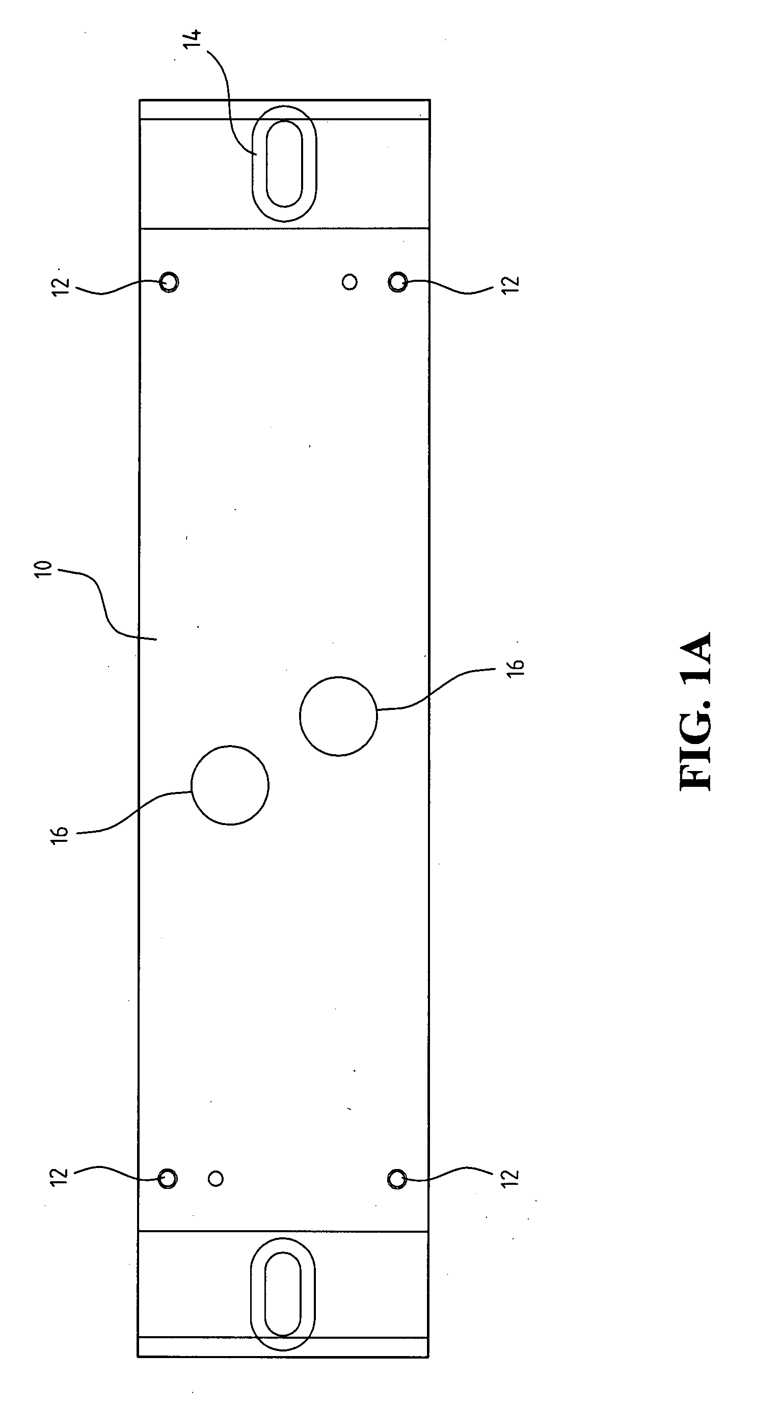
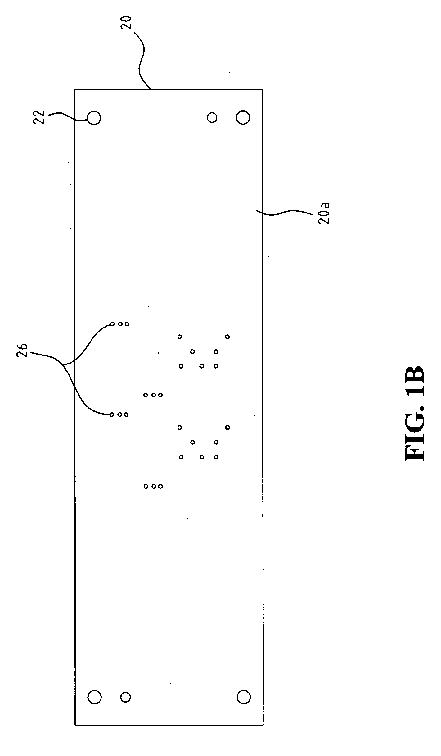
[0014]Referring to FIGS. 1A to 1C, FIGS. 1A to 1C are a plurality of plan views showing an electrical testing system in accordance with an embodiment of the present invention. The test fixture 10 used in the system is shown in FIG. 1A. A test board 20 used in the system is shown in FIG. 1B to FIG. 1C. FIG. 1B is the plan view showing a front side 20a of the test board 20, and FIG. 1C is the plan view showing a back side 20b of the test board 20.

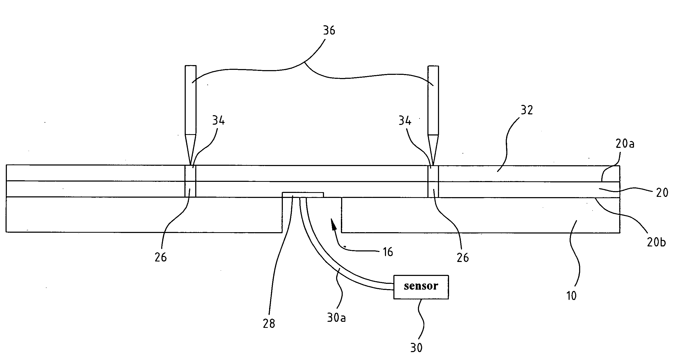
[0015]Referring to FIGS. 2A-2B, FIGS. 2A-2B are a plurality of sectional views showing the electrical testing system in accordance with a preferred embodiment of the present invention. The completed assembly of the test fixture 10 and the test board 20 for the electrical testing system is shown in FIG. 2A. An actual testing performed on a PCB 32 is shown in FIG. 2B.

[0016]The electrical testing system according to the preferred embodiment of the present invention includes a test board 20 which can be electrically contacted with the PCB 32 (as ...


PUM


Abstract

Electrical testing system which is mainly used for testing double-sided printed board (DSB) (having terminals which are electrically connected with each other are separately provided on the two sides, respectively) is provided. The system includes a test board which is electrically contacted with the PCB, a test fixture which supports the test board and the PCB, testing probes which output an electrical signal, and a sensor which receives the electrical signal through the PCB and the test board. When the PCB is mounted on the test board, the electrical signal outputted from the testing probes sequentially is transmitted to the test board through the PCB, and based upon whether the sensor receives the electrical signal to thereby determine whether the terminals on the PCB corresponding to the testing probes are under the open circuit or the short circuit condition.

Description

BACKGROUND OF THE INVENTION[0001]1. Field of the Invention[0002]The present invention relates generally to an electrical testing system, and in particular to an electrical testing system used for testing the double-sided bare board.[0003]2. The Prior Arts[0004]Electronic assembly testing typically includes of two types: a bare board test and a loaded board test. Herein, the bare board test is performed after the completion of the fabrication of the PCB, which mainly includes the testing of a short circuit, an open circuit or a shorted circuit, and the conductivity of a net list. There are also many other inspection and testing methods during the fabrication process. The loaded board test is more complex than the bare board test, and is to be performed after the electronic assembly is completed.[0005]The testing performed during the electronic assembly includes the following: manufacturing defect analysis (MDA), in-circuit test (ICT), and function test (allowing the products to perfo...

Claims


Application Information

Patent Timeline
Patent Type & Authority Applications(United States)
IPC IPC(8): G01R31/02
CPCG01R31/2808
Inventor HSU, WEN-BI
Owner KINSUS INTERCONNECT TECH
Why Eureka
Try Eureka