Power storage unit and vehicle

a technology for power storage units and vehicles, applied in the direction of cell lids/covers, cell components, electrical equipment, etc., can solve the problems of increasing the temperature of each battery cell, and affecting the operation of the other battery cell valves, so as to reduce the internal resistance of the power storage module, suppress the gas production, and simplify the structure of the power storage unit case

Inactive Publication Date: 2009-01-01
TOYOTA JIDOSHA KK
View PDF1 Cites 14 Cited by
  • Summary
  • Abstract
  • Description
  • Claims
  • Application Information

AI Technical Summary

Benefits of technology

[0016]When the second valve thus opens, the insulative liquid enters the power storage module and contacts the power generation element therein, resulting in an increase in the internal resistance of the power storage module, and it suppresses gas production in said power storage module.
[0017]As such, because gas production at each power storage module may be thus suppressed, the structure of the power storage unit case may be simplified and thus its weight may be reduced. Thus, the power storage unit may be made more compact in size and lighter in weight.

Problems solved by technology

Although the battery pack case is filled with the insulative oil and therefore the respective battery cells are insulated from each other as mentioned above, if the electrolyte solution leaks to the outside of any battery cell, the insulation of the insulative oil weakens accordingly.
If the insulation of the insulative oil weakens, it may cause current to flow between the battery cell producing the gas and other battery cells, and this increases the temperature of each battery cell.
As such, if the valve of any battery cell is opened, it may cause the valves of other battery cells to be opened.
In this case, the pressure in the battery pack case increases excessively.
However, increasing the strength of the battery pack case inevitably results in complication of the structure of the battery pack case, which leads to enlargement of the battery pack, or in a heavier weight of the battery pack case.
Further, having a gas guide mechanism inevitably results in enlargement of the battery pack for accommodating said mechanism, which reduces the freedom in arranging the battery pack.
For example, such enlargement of the battery pack is not desirable especially in a case where the battery pack is mounted in a vehicle because it may result in enlargement of the vehicle, or the like.

Method used


Image

  • Power storage unit and vehicle
  • Power storage unit and vehicle
  • Power storage unit and vehicle

Examples


Embodiment Construction

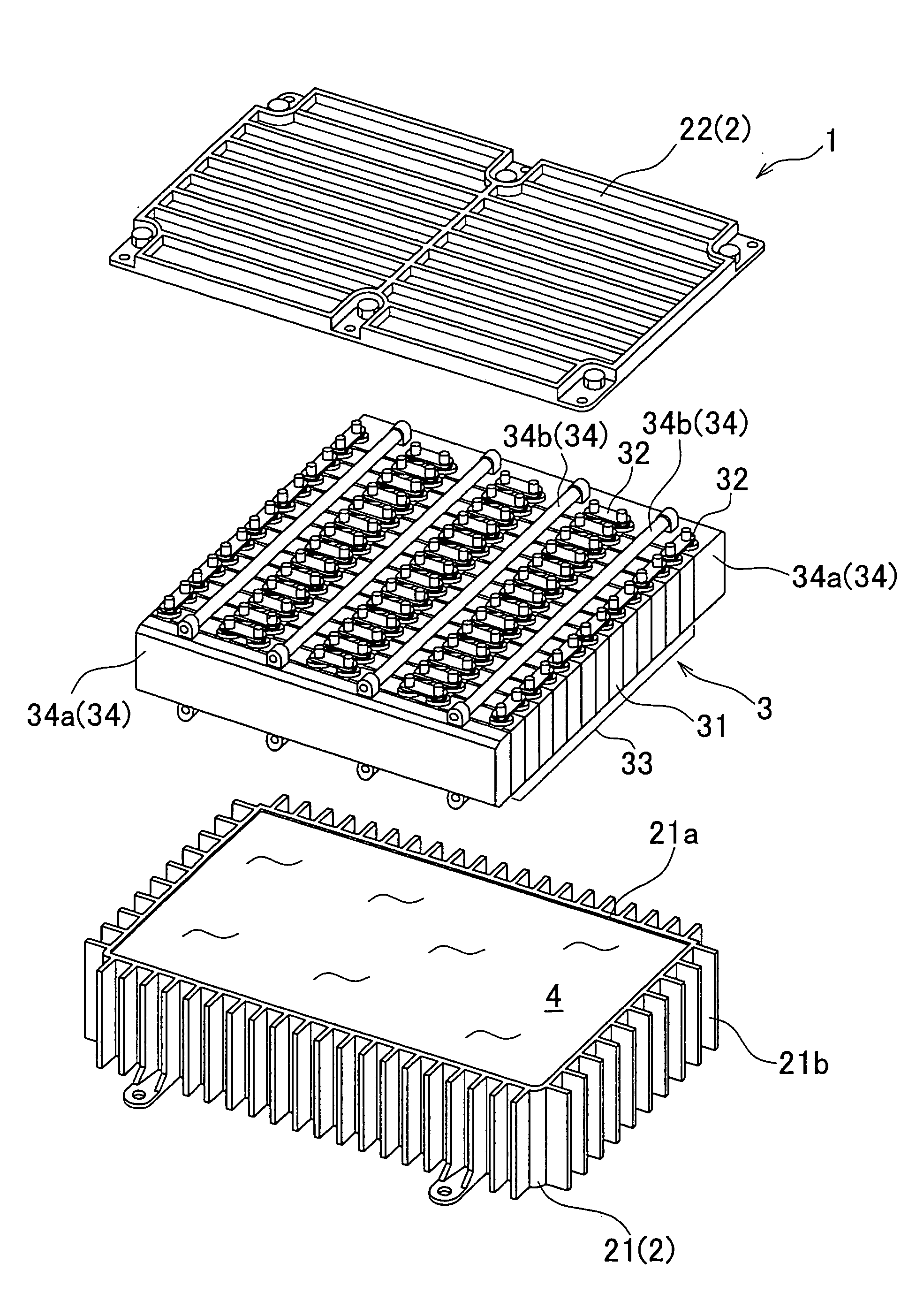
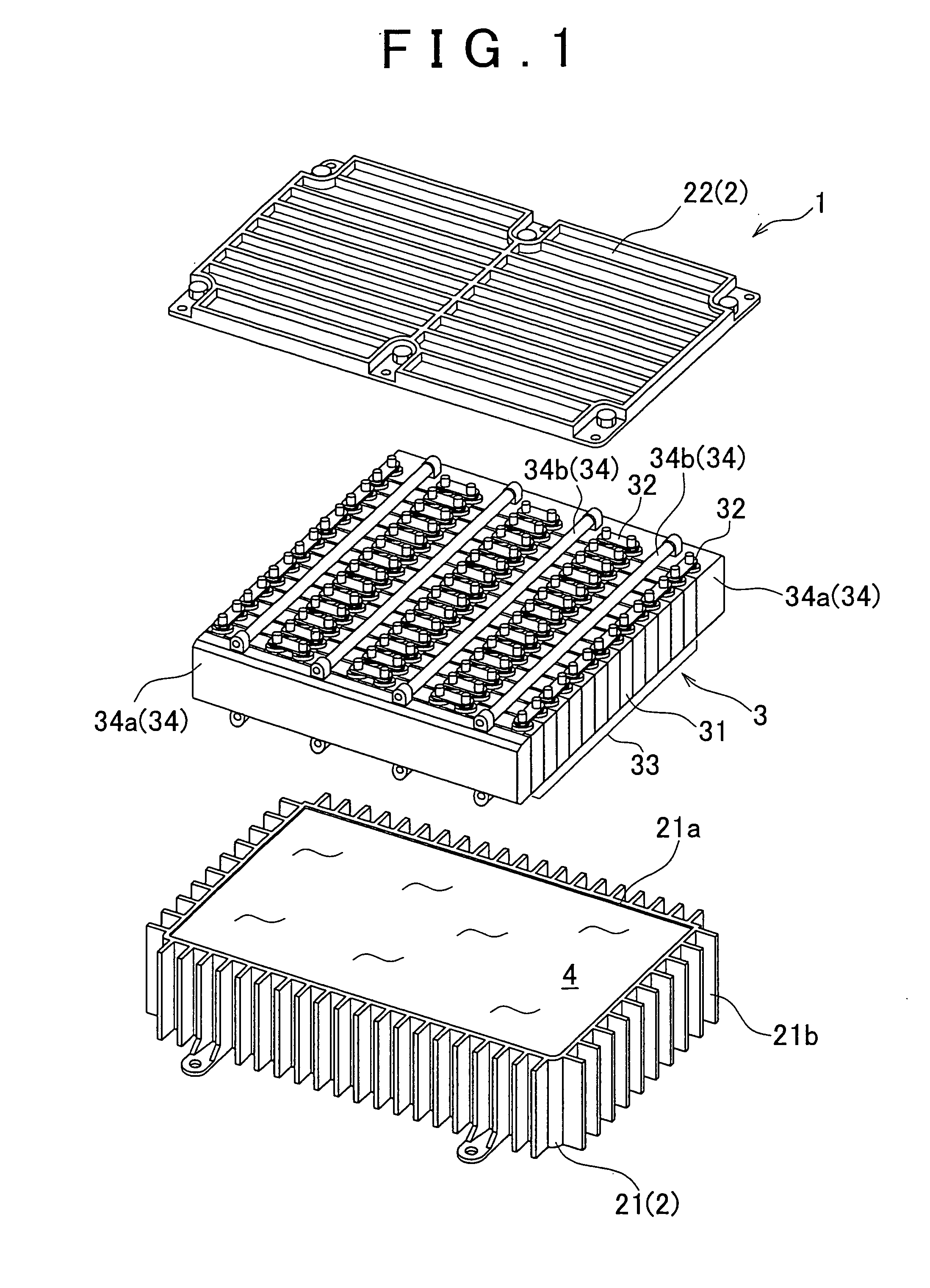
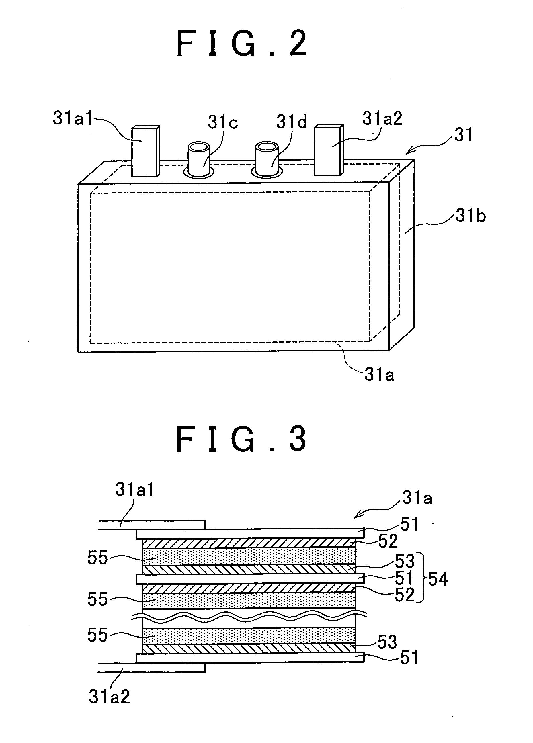
[0024]First, the structure of a battery pack 1 (“power storage unit”) according to the example embodiment of the invention will be described with reference to FIG. 1. FIG. 1 is an exploded perspective view of the battery pack 1. This battery pack 1 is adapted to be mounted in a vehicle.

[0025]The battery pack 1 is constituted of a battery pack case 2 (“power storage unit case”), a battery unit 3 disposed in the battery pack case 2, and an insulative oil 4. The battery pack case 2 is constituted of a container 21 defining a space for storing the power storage assembly 3 and the insulative oil 4 and a lid member 22 covering an opening 21a of the container 21.

[0026]Provided on the outer side face of the container 21 are radiation fins 21b for facilitating heat radiation from the battery pack 1 (i.e., the heat radiation from the battery unit 3). Note that the radiation fins 21b may be omitted if appropriate. The lid member 22 is fixed to the container 21 using fasteners, such as bolts, w...


PUM

PropertyMeasurementUnit
internal pressureaaaaaaaaaa
pressureaaaaaaaaaa

Abstract

A power storage unit has: a plurality of power storage modules each constituted of a power generation element which in a power generation element case containing the power generation element; and a power storage unit case containing the power storage modules and an insulative liquid, wherein at least two of the power storage modules have a first valve that switches from a closed state to an open state in response to the pressure in the power generation element case increasing up to a first threshold and a second valve that switches from a closed state to an open state in response to the pressure at the outside of the power generation element case increasing up to a second threshold.

Description

INCORPORATION BY REFERENCE[0001]The disclosure of Japanese Patent Application No. 2007-168402 filed on Jun. 27, 2007 including the specification, drawings and abstract is incorporated herein by reference in its entirety.BACKGROUND OF THE INVENTION[0002]1. Field of the Invention[0003]The invention relates to a power storage unit having a case, a plurality of power storage modules provided in the case, and an insulative liquid provided in the case. The invention relates also to a vehicle incorporating such a power storage unit.[0004]2. Description of the Related Art[0005]A typical battery pack is constituted of a plurality of battery cells (e.g., secondary batteries) electrically connected in series and disposed in a battery pack case. For example, a battery pack is known which has a battery pack case containing an insulative oil to facilitate the heat radiation from the battery cells and to insulate the battery cells from each other (Refer to Japanese Patent Application Publications ...

Claims


Application Information

Patent Timeline
Patent Type & Authority Applications(United States)
IPC IPC(8): H01M2/12H01M50/209H01M50/271
CPCH01M2/1077H01M2/1223H01M2/1235H01M10/5075H01M10/5016H01M10/5032H01M10/5046H01M10/5004H01M10/625H01M10/647H01M10/6551H01M10/6567H01M10/613Y02E60/10H01M50/317H01M50/342H01M50/209H01M50/271
Inventor NAKAMURA, YOSHIYUKI
Owner TOYOTA JIDOSHA KK
Why Eureka
Try Eureka