Intraocular Lens Injector

Inactive Publication Date: 2009-01-01
BAUSCH & LOMB INC
View PDF11 Cites 31 Cited by
  • Summary
  • Abstract
  • Description
  • Claims
  • Application Information

AI Technical Summary

Benefits of technology

[0010]Aspects of the present invention are directed to an inj

Problems solved by technology

Plunger stability may be particularly troublesome for molded plastic injectors, but also occurs in other injectors.
Further, a plunger may be particularly unstable at points of the stroke near full retraction, where interface I between the plunger and the injector body is relatively small.
However, in at least some instances, increasing injector length is undesirable and may make the injector more cumbersome to handle, and reduced stroke is undesirable because it reduces control of the inject

Method used


Image

  • Intraocular Lens Injector
  • Intraocular Lens Injector
  • Intraocular Lens Injector

Examples


Example

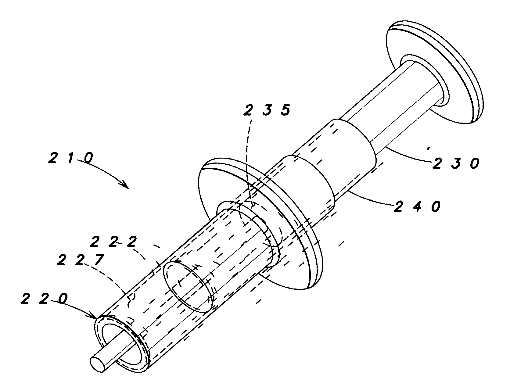
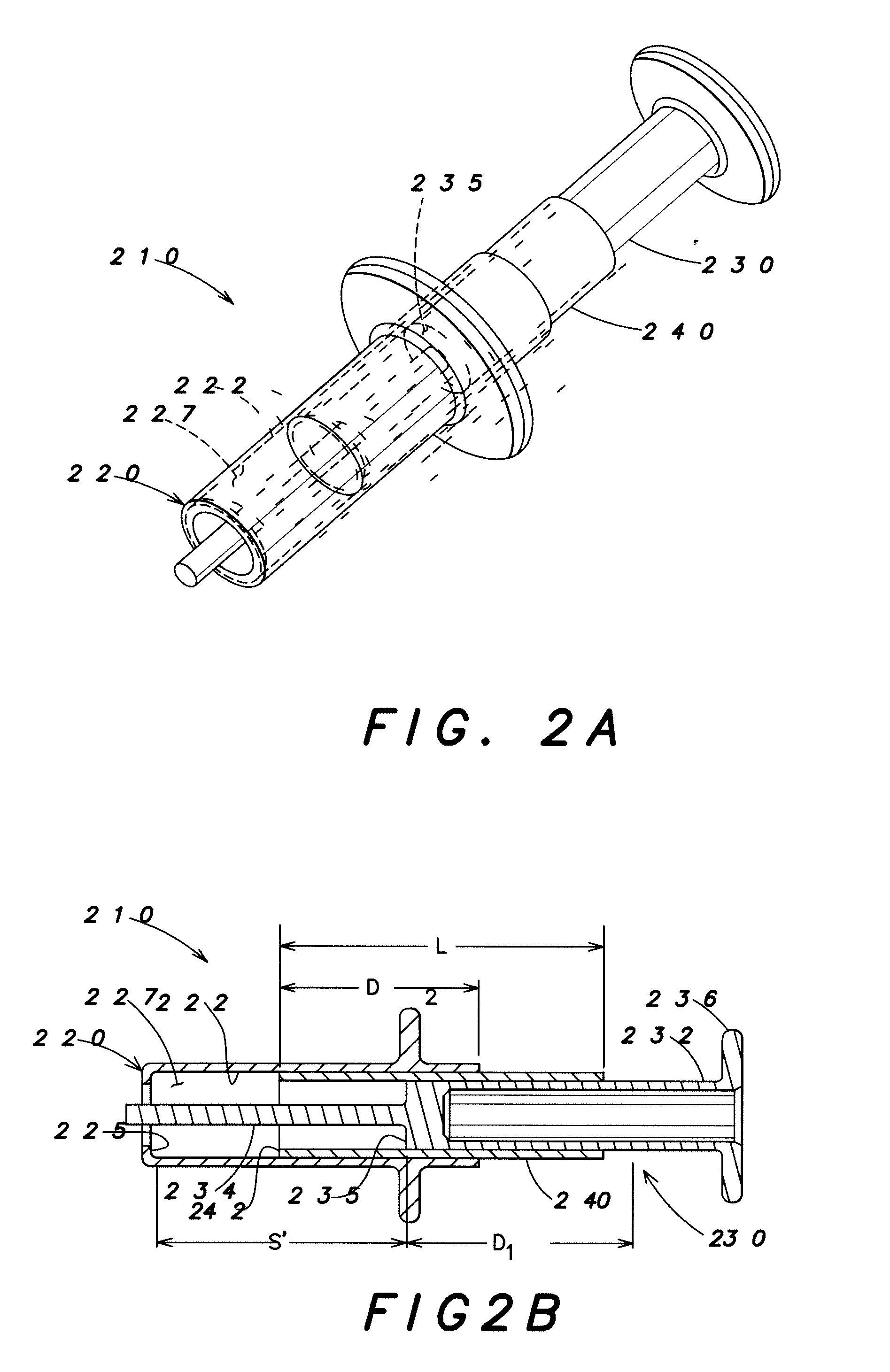
[0022]FIG. 2A is a schematic view of an example embodiment of an IOL injector 210 according to aspects of the invention; and FIG. 2B is a cross sectional view of the embodiment of an IOL injector. IOL injector 210 includes an injector body 220, a plunger 230, and a sleeve 240 having a length L. Sleeve 240 is disposed intermediate at least a portion of the plunger and at least a portion of the injector body. Plunger 230 is shown at full retraction. The nozzle and the IOL (as shown in FIG. 1A and 1B) are omitted from FIGS. 2A and 2B and from the FIGs. discussed below to avoid obfuscation. It is to be understood that an injector as shown in any of the FIGs. may include a nozzle of any suitable configuration, the nozzle having a hole for delivery of an IOL into an eye.

[0023]Injector body 220 has a lumen wall 222 defining a lumen 227. Plunger 230 is configured and arranged to move through the lumen. The wall may completely enclose the lumen along the lumen's entire length or have one or ...


PUM


Abstract

An IOL injector, comprising an injector body having a lumen wall defining a lumen, a plunger configured and arranged to move through the lumen, and a sleeve, the sleeve configured and arranged so as to contact at least a portion of the lumen wall and to slidably engage with at least a portion of the plunger.

Description

FIELD OF THE INVENTION [0001]The present invention relates to intraocular lens (IOL) injectors, and more particularly to IOL injectors providing plunger control.BACKGROUND OF THE INVENTION [0002]IOLs are artificial lenses used to replace or supplement the natural crystalline lenses of patients' when their natural lenses are diseased or otherwise impaired. IOLs may be placed in either the posterior chamber or the anterior chamber of an eye. IOLs come in a variety of configurations and materials.[0003]Various instruments and methods for implanting such IOLs in an eye are known. Typically, an incision is made in a patient's cornea and an IOL is inserted into the eye through the incision. In one technique, a surgeon uses surgical forceps to grasp the IOL and insert it through the incision into the eye. While this technique is still practiced today, more and more surgeons are using IOL injectors, which offer advantages such as affording a surgeon more control when inserting an IOL into a...

Claims


Application Information

Patent Timeline
IPC IPC(8): A61F9/007
CPCA61F2/1662A61M5/31505A61F2/167A61F2/16A61F9/007
Inventor RATHERT, BRIAN D.
Owner BAUSCH & LOMB INC
Why Eureka
Try Eureka