Passenger Conveyor

a technology for conveyors and passengers, applied in the direction of escalators, transportation and packaging, etc., can solve the problems of devices with a further large capacity, production cost and availability problems, etc., and achieve the effects of increasing the space for installation, increasing the number of driving devices, and high production costs

Inactive Publication Date: 2009-01-08
TOSHIBA ELEVATOR KK
View PDF4 Cites 0 Cited by
  • Summary
  • Abstract
  • Description
  • Claims
  • Application Information

AI Technical Summary

Benefits of technology

[0017]In the passenger conveyor according to the above-described aspect of the present invention, it is possible to install an appropriate number of driving devices each having an appropriate capacity, which is larger than a conventional one, without changing the conventional truss dimension. This is achieved by forming the step-attitude changing zone for changing the attitude of each step on the return path side, on the traveling path of the steps on the return path side in the passenger conveyor in which the driving device is installed in the intermediate portion. As a result, it is possible to constitute an efficient passenger conveyor in which problems, such as a high production cost due to an increase in space for installation or an increase in the number of driving devices in the intermediate portion, are solved.

Problems solved by technology

A driving device with a further large capacity, as well as a chain and a driving wheel having enough strength to handle such a driving device, are not widely employable.
This leads to problems regarding production cost and availability.

Method used


Image

  • Passenger Conveyor
  • Passenger Conveyor
  • Passenger Conveyor

Examples


first embodiment

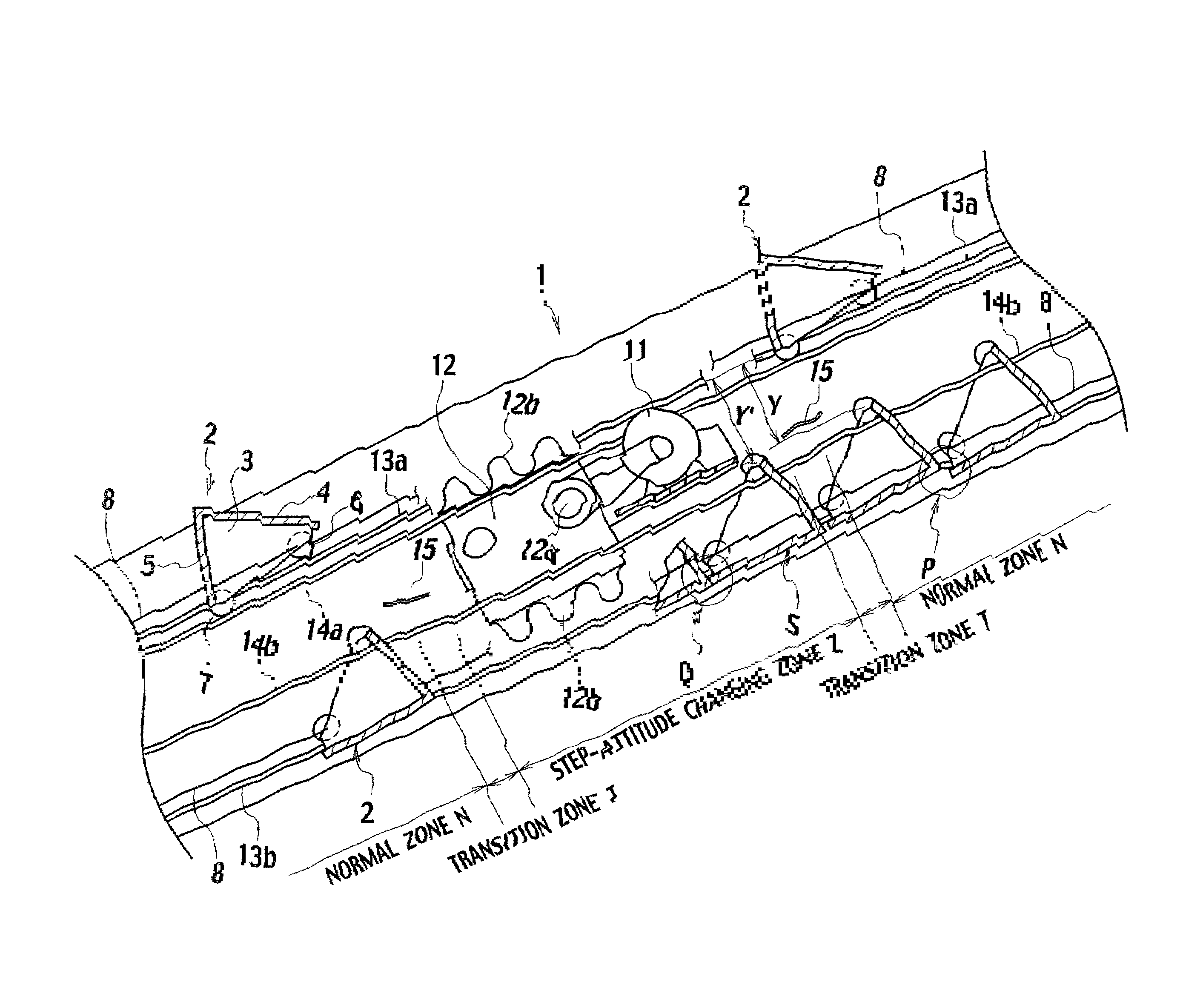
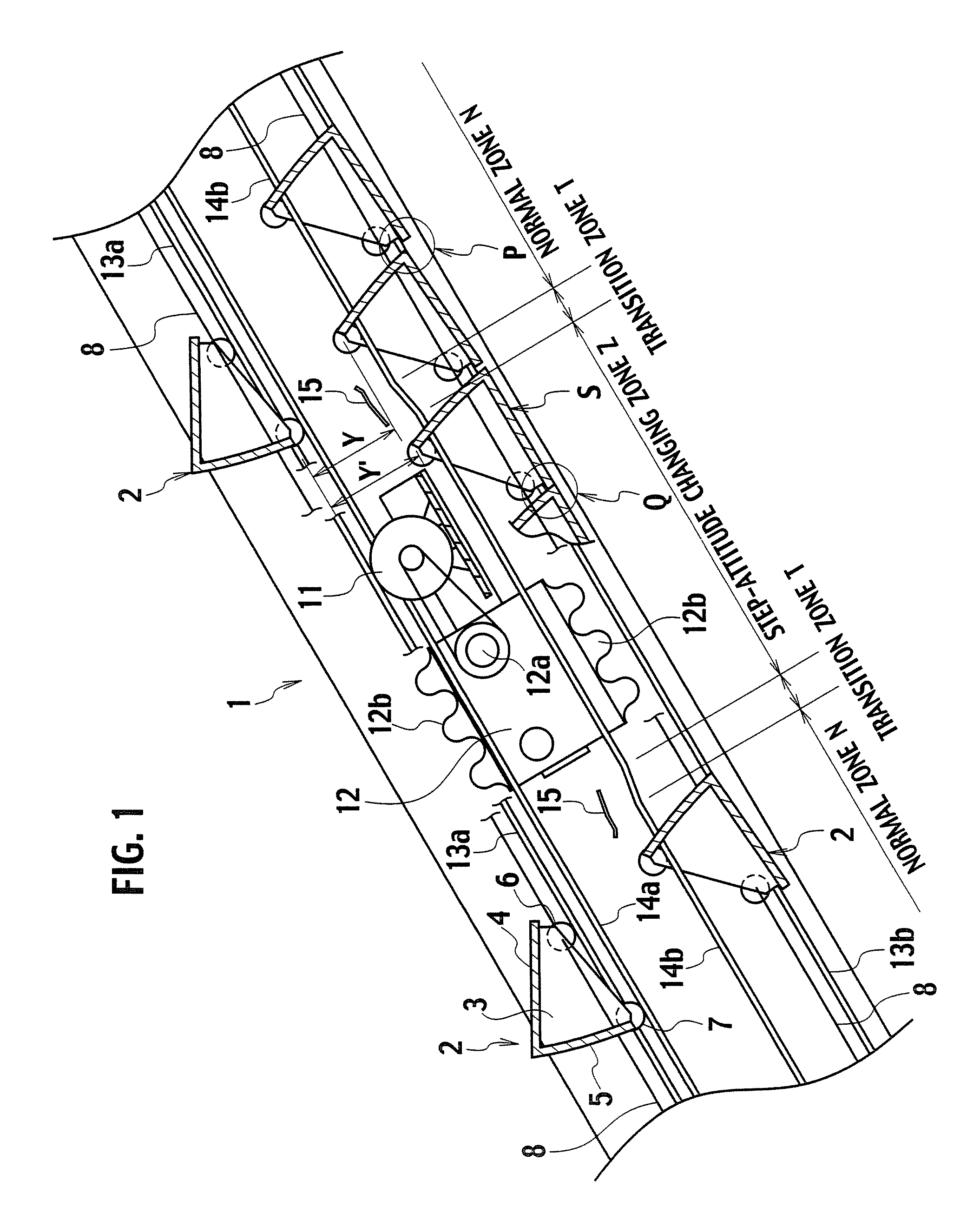
[0023]FIG. 1 is a side view showing an example of an escalator as an a passenger conveyor according to a first embodiment of the present invention, and particularly showing principal parts of and around a driving device provided in an intermediate portion of the escalator.

[0024]A passenger conveyor 1 shown in FIG. 1 includes a plurality of steps 2. Each of the steps 2 includes a frame 3, a footboard 4, a stair riser 5, front-wheel rollers 6 and rear-wheel rollers 7. The frame 3 has a side contour of a substantially fan shape. The footboard 4 is attached to the frame 3, and includes a tread on which a passenger stands. The stair riser 5 is attached to an arc portion of the frame 3 while being connected to one end portion of the footboard 4. The front-wheel rollers 6 and the rear-wheel rollers 7 are provided respectively in a vicinity of the front end of the frame 3 and in a vicinity of the rear end of the frame 3, so as to serve as step rollers attached rotatably to the frame 3. The ...

second embodiment

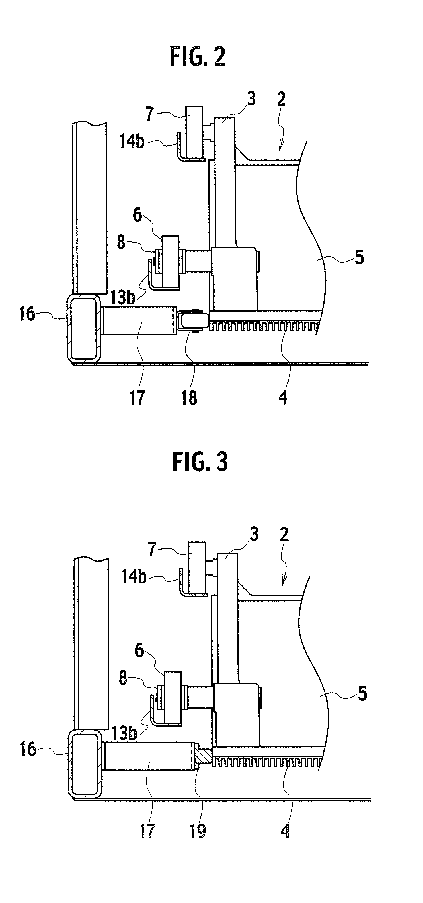
[0044]FIG. 3 shows a cross-sectional view of a part, on a return path side, of a step-attitude changing zone Z of a passenger conveyor according to a second embodiment of the present invention.

[0045]In FIG. 3, the same members as those in FIG. 2 showing the first embodiment are denoted by the same reference numerals, and redundant descriptions will be omitted below.

[0046]In the passenger conveyor of the second embodiment shown in FIG. 3, the fixing members 17 are provided to the truss member 16 to extend toward the side faces of the footboard 4 of each step 2. In addition, a guide member 19 is provided to the tip end of each fixing member 17 in a manner of abutting on the corresponding side face of the footboard 4, or of being adjacent to the corresponding side face of the footboard 4 with some space in between. The guide member 19 is formed of a low frictional resin or the like, which is a low frictional material. Each of the guide members 19 is provided so as to face both side sur...

third embodiment

[0049]FIG. 4 shows a cross-sectional view of a part, on a return path side, of a step-attitude changing zone Z of a passenger conveyor according to a third embodiment of the present invention.

[0050]In FIG. 4, the same members as those in FIG. 2 and FIG. 3 are denoted by the same reference numerals, and redundant descriptions will be omitted below.

[0051]In FIG. 4, a plate member 20 is attached to the side face of the rear-wheel guide rail 14b on the return path side. The plate member 20 is formed of a low frictional resin or the like, which is a low frictional material, and also is arranged in a manner of abutting on the rear-wheel rollers 7 of the step 2, or of being adjacent to the rear-wheel rollers 7 with some space in between. The plate members 20 are provided so as to face both side surfaces of the footboard 4 of the step 2, and also one or a plurality of the plate members 20 are provided along the traveling direction of the steps 2.

[0052]In the third embodiment shown in FIG. 4...


PUM


Abstract

Provided is a passenger conveyor including a plurality of steps (2) having step rollers (6 and 7), a step chain (8) circulatingly moving in conjunction with each of the plurality of steps (2), guide rails (13a, 13b, 14a and 14b) provided in an intermediate portion of a truss and guiding the step rollers (6 and 7) of each step (2), and an intermediate driving device (12) provided in the intermediate portion of the truss and configured to transmit a driving force to the step chain (8). A step-attitude changing zone (Z) for changing the attitude of each step (2) on a return path side is provided on the traveling path of the steps (2) on the return path side.

Description

TECHNICAL FIELD[0001]The present invention relates to a passenger conveyor having a driving device installed in an intermediate portion of the passenger conveyor. In particular, the present invention relates to a passenger conveyor in which a space for the installation of the driving device is secured.BACKGROUND ART[0002]A passenger conveyor, such as an escalator and a moving walkway, includes a plurality of steps each provided with step rollers on the front and rear sides thereof. These steps are linked to one another in an endless manner with a step chain. The driving of the step chain causes all the steps to move to circulate between an entrance and an exit in a synchronized manner with no space between each adjacent two steps. In the case of an escalator, each step is guided with the rollers supported on step guide rails installed in a truss while traveling on the forward path side. Accordingly, while a footboard of each step is held horizontal, the step travels in a horizontal ...

Claims


Application Information

Patent Timeline
Patent Type & Authority Applications(United States)
IPC IPC(8): B66B23/02
CPCB66B23/14B66B23/02
Inventor KIKUCHI, TAKAYUKIISHIKAWA, YOSHINOBUMATSUMOTO, YASUHIRO
Owner TOSHIBA ELEVATOR KK
Why Eureka
Try Eureka