

Method of producing stamper for optical recording medium, method of producing substrate, and method of producing optical recording medium
a technology of optical recording medium and stamper, which is applied in the direction of mechanical recording, instruments, other domestic objects, etc., can solve the problems of poor visibility of recorded visible images and complicated operations for producing optical recording media, and achieve excellent image visibility, improve image visibility on label surfaces, and improve image visibility
Inactive Publication Date: 2009-01-08
FUJIFILM CORP
View PDF4 Cites 0 Cited by
- Summary
- Abstract
- Description
- Claims
- Application Information
AI Technical Summary
Benefits of technology
[0010]In view of the above problem, an object of the present invention is to provide a method for producing a stamper useful for producing an optical recording medium excellent in visibility of an image on a label surface, and a method for producing a substrate.
[0011]Another object of the present invention is to provide a method for producing an optical recording medium excellent in visibility of an image on a label surface.
[0013]In the first aspect, the obtained original stamper can be used for producing a stamper for an optical recording medium. Further, by using the stamper, an optical recording medium excellent in the visibility of an image on a label surface can be produced.
[0021]By using the substrate produced by the method of the second aspect, an optical recording medium excellent in the visibility of an image on a label surface can be produced.
[0024]As described above, by using the stamper producing method, or the substrate producing method of the present invention, the optical recording medium excellent in the visibility of an image on a label surface can be obtained.
[0025]Further, by using the optical recording medium producing method of the present invention, the visibility of an image on a label surface can be improved.
Problems solved by technology
Therefore, complicated operations are required for producing the optical recording media.
Thus, additional printers are not needed, and also the complicated operations of attaching the label sheet are not required.
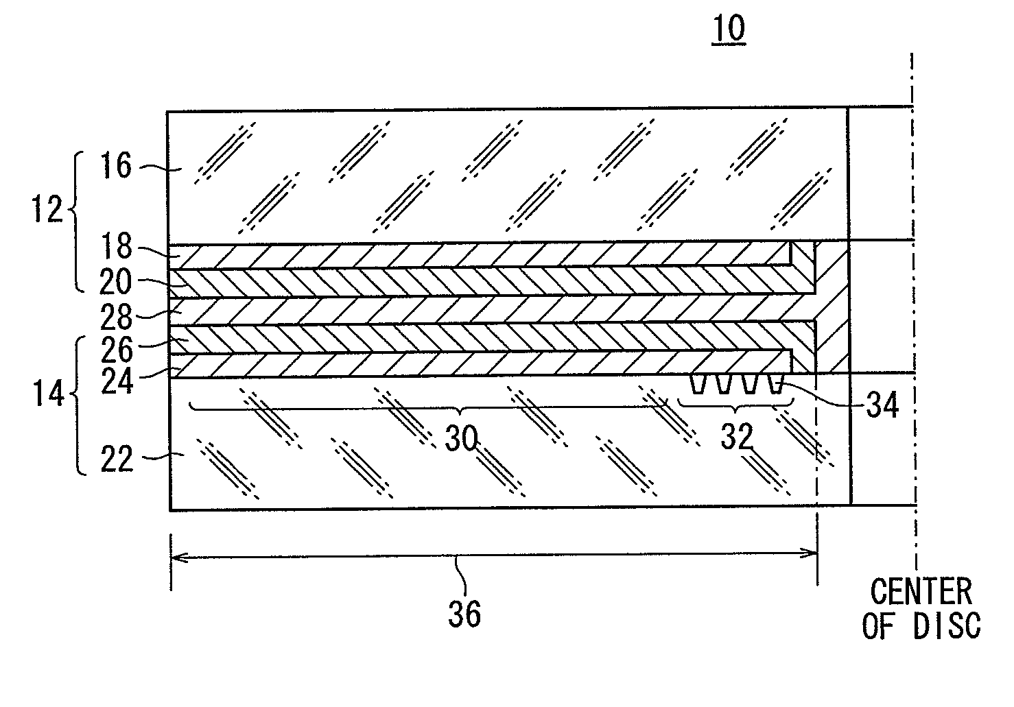
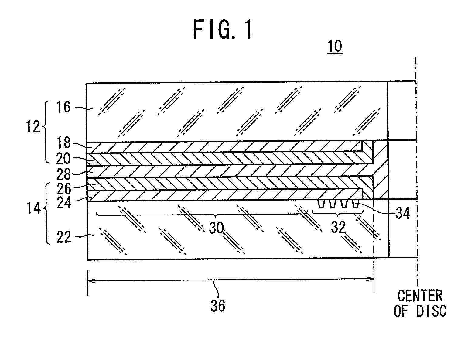
In this case, the grooves on the other substrate act as a diffraction grating for external lights to cause strong interference, thereby resulting in poor visibility of a recorded visible image.
Method used
View moreImage
Smart ImageViewing Examples

Examples
example 1
[0191]The original stamper 76 was produced by steps S1 to S6 shown in FIG. 5 of the method of the above embodiment. The conductive ring 52A of the first modification example shown in FIG. 9 was used in this example, and the inner diameter D1 of the major surface was 193 mm and the inner diameter D2 of the other major surface was 180 mm.
[0192]As shown in FIG. 24, the original stamper 76 was flat without warping after the blasting treatment. Thus, a second-generation stamper 92 could be produced by using the original stamper 76, and further a master stamper 40 could be produced by using the second-generation stamper 92.
Login to View More PUM
| Property | Measurement | Unit |
|---|---|---|
| roughness | aaaaa | aaaaa |
| roughness | aaaaa | aaaaa |
| radius | aaaaa | aaaaa |
Abstract
A method of producing a stamper for roughening a substrate of an optical recording medium contains the steps of placing a conductive ring having a hole at the center thereof on a major surface of an original metal plate, electroforming a metal layer over a portion of the metal plate exposed in the hole of the conductive ring, an inner end-face of the conductive ring, and a portion of a major surface of the conductive ring, and entirely or partly roughening a major surface of the metal layer by a blasting treatment to obtain an original stamper.
Description
BACKGROUND OF THE INVENTION[0001]1. Field of the Invention[0002]The present invention relates to a method of producing a stamper for an optical recording medium, a method of producing a substrate, and a method of producing an optical recording medium, particularly a method of producing a stamper for an optical recording medium containing a substrate having an entirely or partly roughened major surface, a method of producing such a substrate, and a method of producing such an optical recording medium.[0003]2. Description of the Related Art[0004]In several known optical recording media such as CD-Rs and DVD-Rs, electronic information is recorded on a recording surface, and a label is attached to the reverse surface. Visible information of the contents of the electronic information, such as a song title of music data or a title of recorded data, is printed on the label, and the reverse surface is called a label surface.[0005]Such optical recording media are produced by printing a title...
Claims
Login to View More Application Information
Patent Timeline
 Patent Type & AuthorityApplications(United States)
IPC IPC(8): C25D1/10
CPCG11B7/261
InventorCHE, YANLONGSHIBATA, MICHIHIRO
OwnerFUJIFILM CORP