Modular flying vehicle

a flying vehicle and module technology, applied in the field of flight vehicles, can solve the problems of failure and loss of helicopters, lack of vertical takeoff or landing (vtol) or even short takeoff or landing (stol), and inconvenient airplanes, so as to improve lift characteristics, reduce cost, and increase reliability

Inactive Publication Date: 2009-01-08
SHAW DONALD ORVAL
View PDF11 Cites 317 Cited by
  • Summary
  • Abstract
  • Description
  • Claims
  • Application Information

AI Technical Summary

Benefits of technology

[0011]The invention includes a method of operating a flight vehicle having a plurality of propellers and an airframe, involving positioning each of the plurality of propellers with a tilt angle of approximately zero with respect to the airframe plane; providing power to all of the plurality of motors, wherein the power is sufficient to lift the air vehicle off of the ground so the vehicle is airborne; with the vehicle airborne, maintaining or increasing power to a first propeller subset comprising one or more of the plurality of motors; with the vehicle airborne, reducing power to a second propeller subset comprising one or more of the plurality of motors, while simultaneously; with power reduced or eliminated to the second propeller subset, tilting one or more of the propellers of the second propeller subset forward with respect to the airframe front to a tilt angle of between 60 and 95 degrees; and with the one or more of the propellers of the second propeller subset tilted forward with respect to the airframe front to a tilt angle of between 60 and 95 degrees, increasing power to the second propeller subset. After increasing power to the second propeller subset while tilted forward, power may be reduced and even eliminated to one or more propellers of the first propeller subset.
[0020]A vehicle according to the invention could be launched in various methods. The vehicle could launch in a STOL or VTOL technique from land or sea, or from platforms (such as buildings, movable platforms, or ships) on land or sea. The vehicle could include a parachute and / or parafoil or similar device secured to the airframe in order to be launched and / or delivered via air dropping (e.g., from a cargo plane such as a military C-5 or C-130). A drogue chute could stabilize the fall, the engines could start to idle as the drogue chute is retrieved via a mechanism, and the engines could then start to apply full power as the drogue chute is retrieved. The vehicle could also be dropped with just a streamer to stabilize the vehicle, and then start the motors once stability is achieved. Even a freefall with no decelerator may work, with the propellers themselves providing stability and slowing the fall of the vehicle until the engines are fully started. The vehicle could also include an emergency parachute or similar device to be deployed in case of an emergency, such as loss of power to all engines. The emergency parachute could be deployed using an explosive device that throws the parachute into a deployed configuration. A so-called ballistic parachute could be used as an emergency parachute.
[0022]The air vehicle may be configured with interchangeable components, including engines, propellers, and corresponding supports. This allows different components to be exchanged in a relatively rapid fashion for repairs and / or different performance requirements. For example, a set of short propellers could be used for applications where rapid acceleration and high speed were desired for the air vehicle, with a set of longer propellers replacing the shorter propellers for use in applications where high lift and high altitude performance are desired for the air vehicle.
[0023]Large multi-engine versions can be made, with each propeller driven by not just one but several engines. The added engines not only allow for additional thrust but can also provide redundancy in case of engine loss / failure. The engines can be diesel, (including turbodiesel), electric, hybrid, hydrogen, and other fuel burning motors that turn the propellers sufficiently to propel the aircraft with the payload through the air with good performance.
[0029]Navigation systems can include GPS systems and other modern navigation methods. An autopilot can be used, including many of the helicopter-type state of the art autopilots currently available, such as a Piccolo 2 series autopilot when interfaced with neural net computer software like the one that the Naval Research Laboratory has developed for their SPIDER Helicopter. In addition to other navigation systems, an obstacle avoidance system such as a scanning laser system may be employed to find obstacles in the air vehicle flight path. Difficult-to-spot obstacles such as power lines, etc. may be located using map data, etc. Other aircraft can be avoided through the use of transponder information, by receiving secure data by friendly aircraft as to where they are by GPS coordinates, etc.
[0031]Due to issues with currently available vertical lift vehicles, a need exists for a vertical lift vehicle that has improved lift characteristics, reduced cost, and increased reliability. The present invention addresses these needs.

Problems solved by technology

While airplanes have excellent lifting capacity and altitude capabilities, most airplanes lack vertical takeoff or landing (VTOL) or even short takeoff or landing (STOL) capabilities, and they typically require a large open space for takeoff and landing.
In many rugged landing sites, airplanes are not suitable.
Helicopters are sometimes subject to accidents and failures, such as engine or rotor failures, which in some situations will lead to a failure and loss of the helicopter.
Additionally, many helicopters have difficulty operating at high altitudes.

Method used


Image

  • Modular flying vehicle
  • Modular flying vehicle
  • Modular flying vehicle

Examples


Embodiment Construction

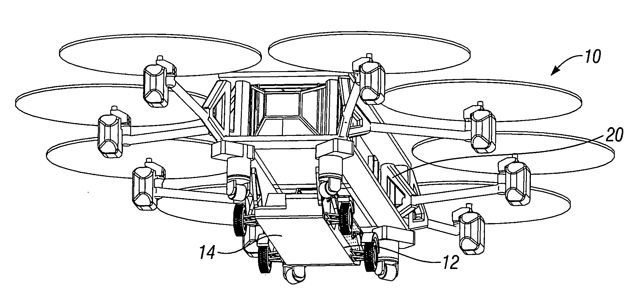
[0074]FIG. 1 depicts a vehicle 10 according the invention. The vehicle 12 includes a transport module 14 in the form of a ground vehicle 16 mated to an air vehicle 20.

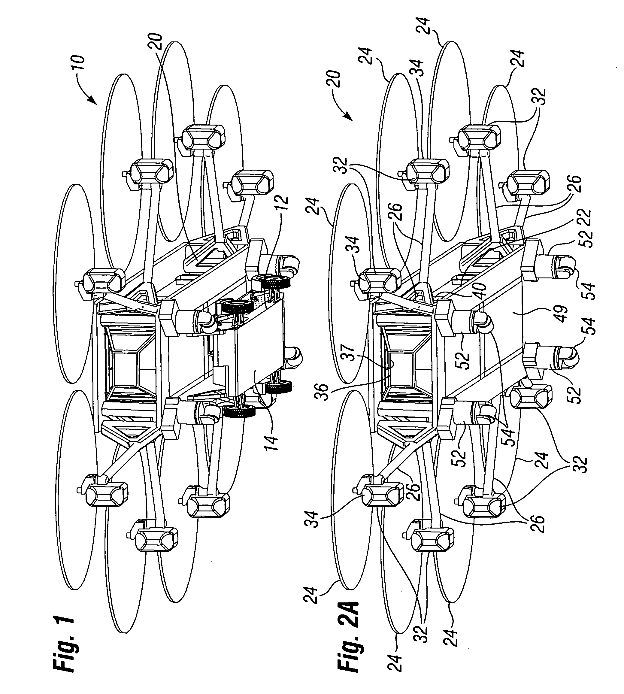
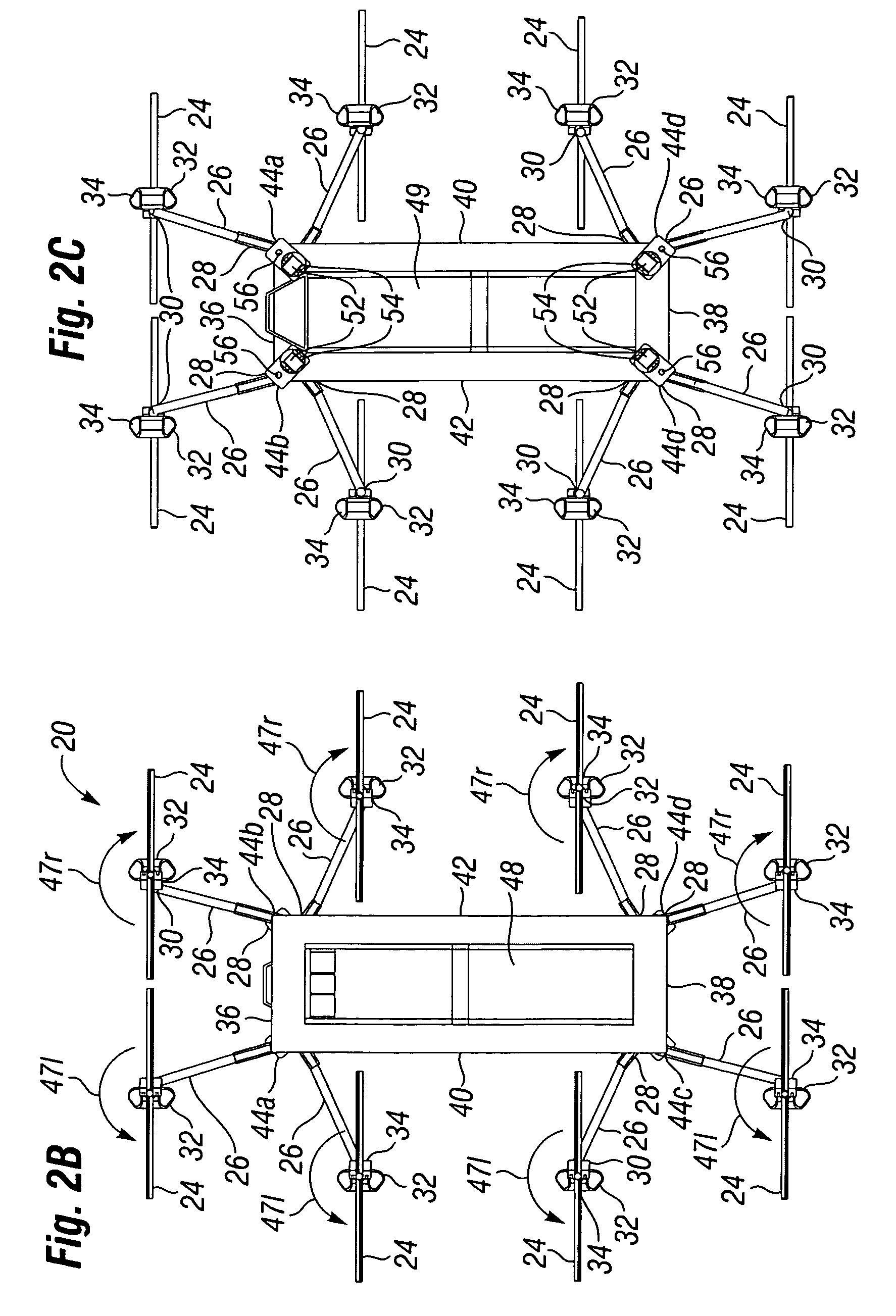
[0075]FIGS. 2A-2E depict an air vehicle 20 according to an embodiment of the invention, comprising a main airframe 22 having a forward axis 23 passing through its middle in back-to-front fashion. Eight (8) propellers 24 extend from the airframe 22 on propeller supports 26. Each propeller support 26 has a proximal end 28 secured to the main airframe 22, and a distal end 30. In the particular embodiment depicted, each propeller 24 is linked to and individually powered by a devoted engine 32, with a linked propeller 24 and engine 32 forming an engine-propeller assembly 34. One engine-propeller assembly 34 is positioned at the distal end 30 of each propeller support 26. Note that the engine-propeller assemblies for use with the invention may have different configurations, depending on the particular application. In one emb...


PUM


Abstract

The invention is a modular vehicle having an air vehicle that can be coupled to cargo containers, land vehicles, sea vehicles, medical transport modules, etc. In one embodiment the air vehicle has a plurality of propellers positioned around a main airframe, which can provide vertical thrust and / or horizontal thrust. One or more of the propellers may be configured to tilt forward, backward, and / or side-to-side with respect to the airframe.

Description

RELATED APPLICATIONS[0001]The present application claims priority under 35 U.S.C. §119(e) to U.S. Provisional Application No. 60 / 901,809 filed on Feb. 16, 2007, the entire contents of which is hereby incorporated by reference.FIELD OF THE INVENTION[0002]The present invention relates to flight vehicles, and more particularly to flight vehicles configured to carry various payloads.BACKGROUND OF THE INVENTION[0003]Heavier-than-air flight vehicles have been known for that last 100 years or so, and include airplanes and helicopters. Such flight vehicles are used in many applications where speed is necessary to transport people and / or cargo to distant locations.[0004]In many applications, it is desirable to transport people and / or materials to distant locations where the terrain is rugged and facilities may be lacking. For example, in many military applications troops and equipment must be delivered rapidly to intercept enemy troops. The use of flight vehicles is often the quickest method...

Claims


Application Information

Patent Timeline
Patent Type & Authority Applications(United States)
IPC IPC(8): B64C27/08
CPCB64C27/20B64C29/0033B64C27/52B64C2201/128B64C2201/027B64U2101/60B64U10/13B64C27/08B64C27/28B64C39/024
Inventor SHAW, DONALD ORVAL
Owner SHAW DONALD ORVAL
Why Eureka
Try Eureka