
Headlamp That may Be Dismantled

a headlamp and dismantling technology, applied in the field of headlamps, can solve problems such as poor approach, and achieve the effect of easy removal from the head

Inactive Publication Date: 2009-01-08
WU JIAN JUN
View PDF5 Cites 1 Cited by
  • Summary
  • Abstract
  • Description
  • Claims
  • Application Information

AI Technical Summary

Benefits of technology

[0007]In this invention, a floodlight that may be easily taken from head is provided and serves as a headlamp that is charged by swaying with one hand and may be dismantled.
[0009]For a further arrangement of this invention, a mounting plate is connected with a turning joint to the fixture mount and the floodlight may be dismantled and then inserted onto the mounting plate. The turning joint is on the fixture mount in an L shape. A guidance groove is formed at each of two sides of downsides of the mounting plate. A lead rail is formed on the lamp body of the corresponding floodlight that is inserted to match with the two sides of downsides. A shift limit lug is provided at a top of the downside of the mounting plate. A shift limit hole is formed in a position where the shift limit lug is corresponding to the lamp body for insertion and matching. The floodlight that is thereby mounted onto the mounting plate is much more firm, and particularly the floodlight is mainly worn on head, so an amplitude of vibration is wider and a degree of fastness of the mounted floodlight is certainly considered. Indeed, in this invention, the mounting plate may also be provided in another form, and once it is arranged in another form, the lamp body corresponding to the floodlight is differently connected. If the mounting plate is arranged in a U shape, the mounting plate clips the floodlight; however, the approach is not better, so it is generally not applied.
[0011]For a further arrangement of this invention, lead grooves are provided at the two sides of an end of handle portion of the rocking handle and at the two sides of the downside of mounting plate for insertion and matching. The shift limit lug of which a cross section is in a T shape is provided at the top of downside of the mounting plate, and the shift limit hole correspondingly wedged to match with the shift limit lug is provided on the rocking handle to prevent the floodlight from falling transversally. The shift limit hole comprises a center hole and an adjacent hole. The center hole is divided into a big-aperture port and a small-aperture port, the inner side of big-aperture port communicates that of the small-aperture port through their corresponding curved faces. The adjacent hole is formed outside of the two curved faces. The shift limit lug is placed from the big-aperture port of center hole and glides to the small-aperture port to transversally and longitudinally wedge to and match with the shift limit hole, which is a scientific way of achievement of simple manufacturing, material saving, higher fastness after installation; indeed, another manner may be applied; for example, the shift limit hole is just a hole, a material made into the part is certainly flexible, so it is not a bit affected.
[0013]For a still further arrangement of this invention, two supports are provided on the fixture. The mounting plate matches with the fixture through the support with a turning joint. A button is provided at a top side of the housing to control the lamp receptacle to be bright or put out, and it is easy to manually to turn round the floodlight, and the floodlight is well secured after turned round. The support on the fixture may also be tightly compressed to revolve around the mounting plate to match with each other, which is assured that the floodlight is secured after being turned round at a random angle. A protruding stands are provided at an angular portion of the mounting plate in the ‘L’ form and at a side of the shift limit lug, and through the protruding stand, internal matching parts are made to more closely touch with each other after the floodlight is inserted for a further enhanced fastness.

Problems solved by technology

If the mounting plate is arranged in a U shape, the mounting plate clips the floodlight; however, the approach is not better, so it is generally not applied.

Method used


Image

  • Headlamp That may Be Dismantled
  • Headlamp That may Be Dismantled
  • Headlamp That may Be Dismantled

Examples


Embodiment Construction

[0022]Now, the present invention will be described more specifically with reference to the following embodiments. It is to be noted that the following descriptions of preferred embodiments of this invention are presented herein for purpose of illustration and description only; it is not intended to be exhaustive or to be limited to the precise form disclosed.

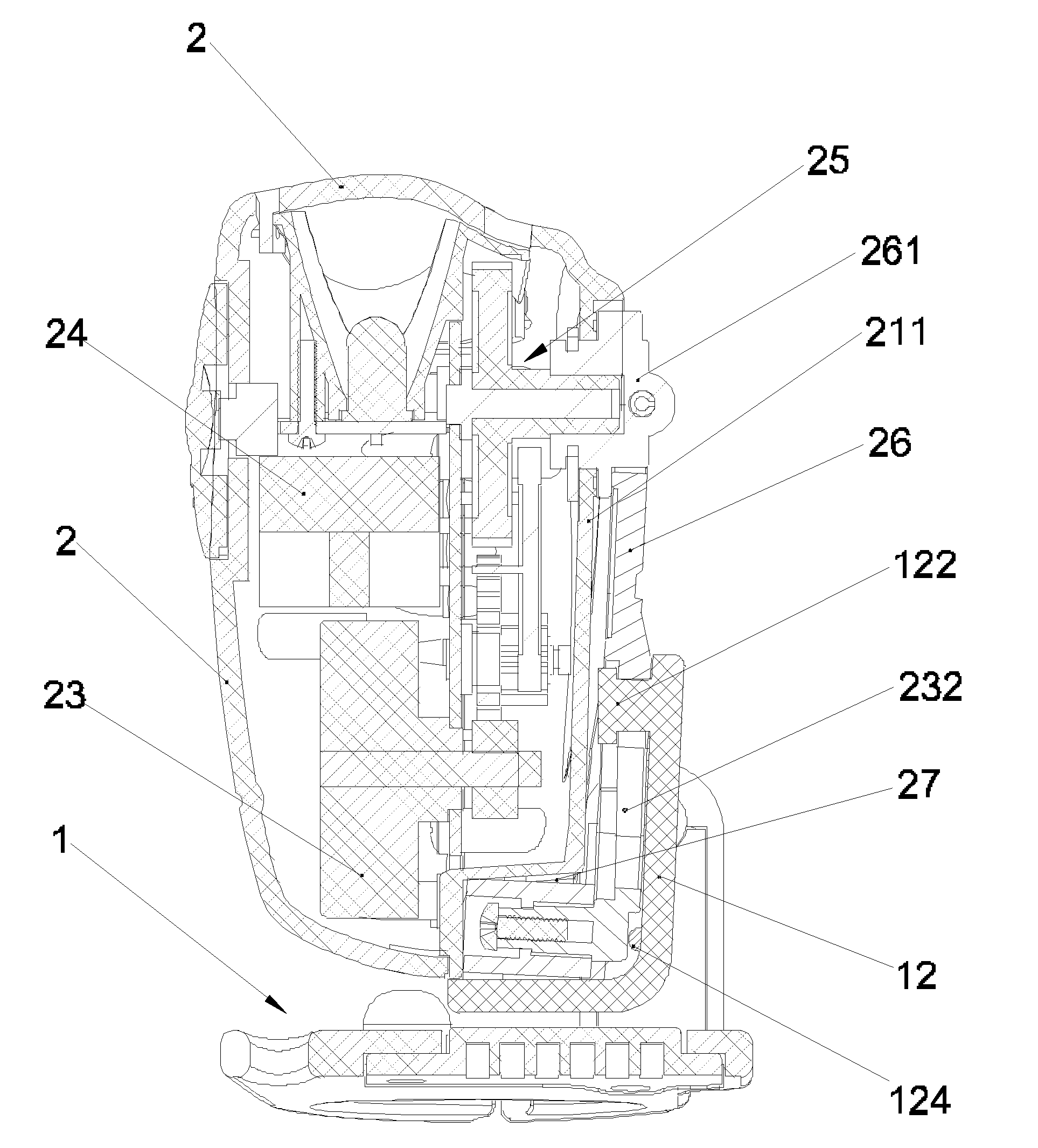
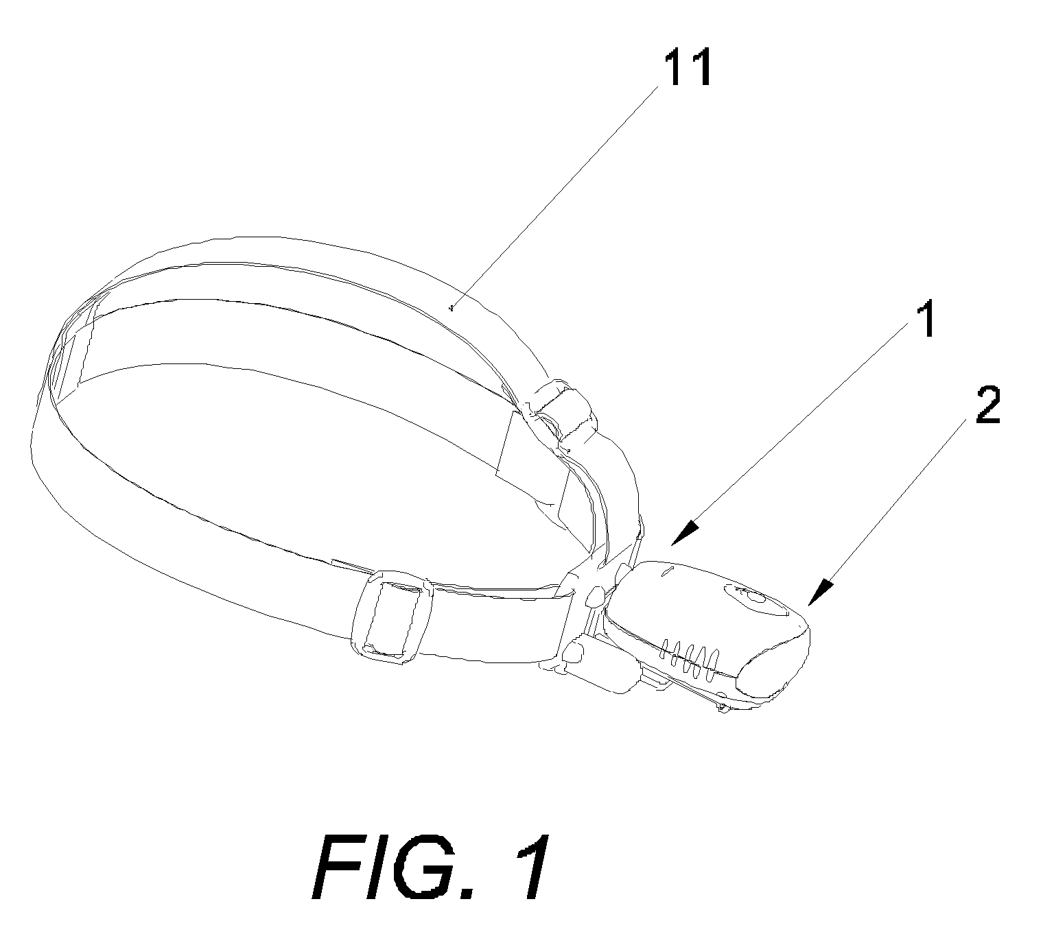
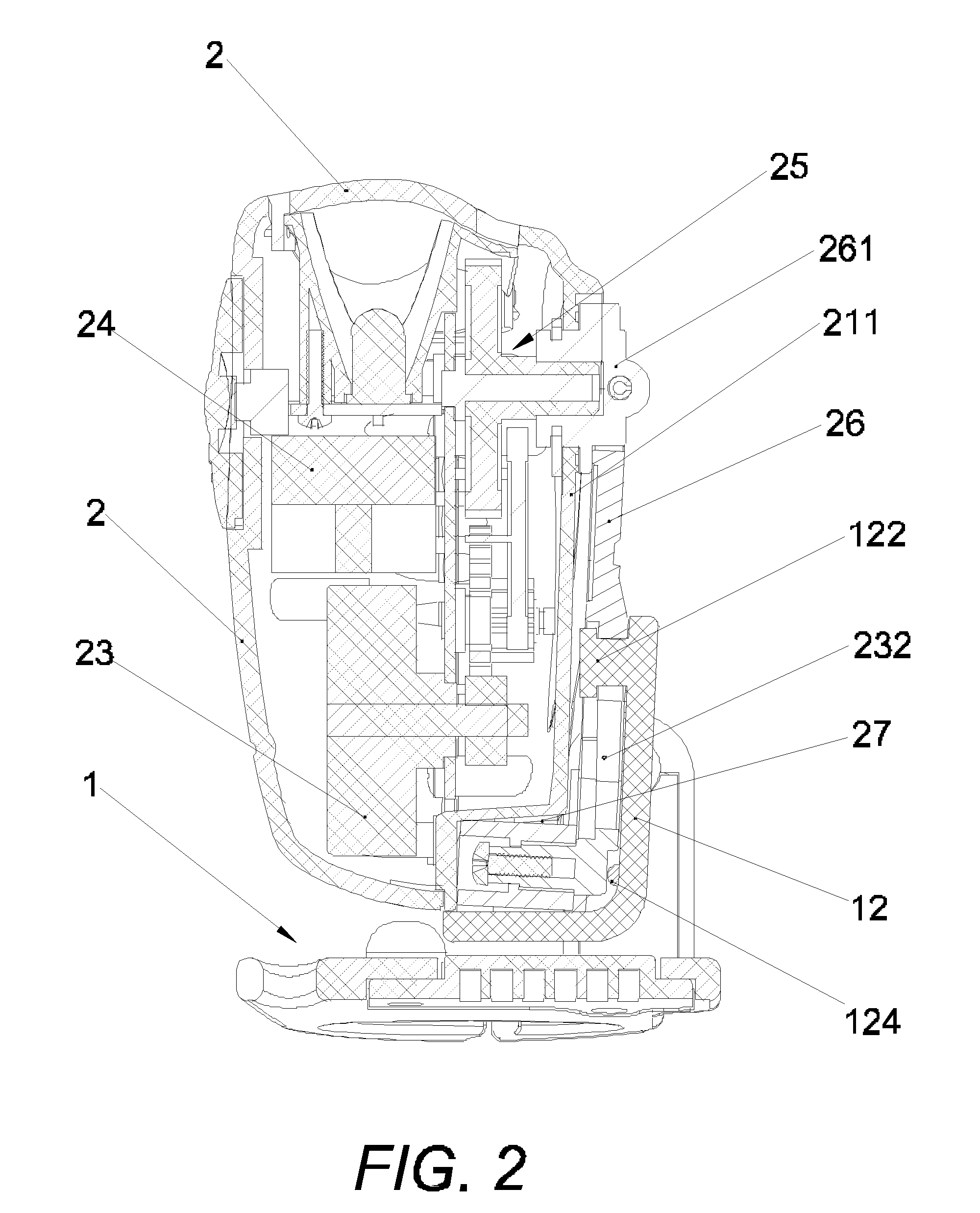
[0023]With reference to FIG. 1, a headlamp that may be dismantled comprises a fixture 1 with a head strap 11, and a floodlight 2. The floodlight 2 comprises a lamp body 21 and a lamp receptacle 22. In an embodiment of this invention, the head body 21 and lamp receptacle 22 of the floodlight 2 is an all-in-one unit. The fixture mount 1 may be dismantled from the floodlight 2 or inserted to match with each other. In the manner, the floodlight 2 may be taken apart from the fixture mount 1 to serve as an ordinary flashlight in daily life for an extra use of the headlamp.

[0024]In the embodiment of this invention, a mounting plate 12 ...


PUM


Abstract

This invention relates to an illuminating tool and particularly to a headlamp that may be worn on a human head for use and may be dismantled. In a skill of this invention, the headlamp that may be dismantled comprises a fixture with a head strap, and a floodlight. The floodlight comprises a lamp body and a lamp receptacle, being characterized in that the head body and lamp receptacle of the floodlight is an all-in-one unit. The fixture mount may be dismantled from the floodlight or inserted to match with each other. In the manner, the floodlight may be taken apart from the fixture mount to serve as an ordinary flashlight for an extra use of the headlamp.

Description

BACKGROUND OF THE INVENTION[0001]1. Field of the Invention[0002]This invention relates to an illuminating tool and particularly to a headlamp that may be worn on a human head for use and may be dismantled.[0003]2. Description of Related Art[0004]A floodlight is a necessary commodity in daily life. Along with an increasing living standard, commodities are highly requested by people continuously. Such a type of floodlight cannot be replaced for a demand. Thus, features of high illumination, long operation time, and low weight are required for use. Along with a progressive technology, the existing product is continuously improved in appearance and inner structure and manufactured for various types. However, the product's shape and comfort index is less considered; for example, most of the floodlights are carried with one hand to illuminate and thus limited in use in some occasions.[0005]A headlamp disclosed in patent No. 200420003520.X is structured with a lamp body, a head wrap, and a...

Claims


Application Information

Patent Timeline
IPC IPC(8): F21V21/084
CPCF21L4/00F21V21/30F21V21/084F21L13/06
Inventor WU, JIAN-JUN
Owner WU JIAN JUN
Learn More