Submersible pump unit
a technology of submersible pumps and parts, applied in the direction of piston pumps, non-positive displacement fluid engines, positive displacement liquid engines, etc., can solve the problems of increasing construction size, increasing the whole assembly, increasing power loss, etc., and achieve the effect of improving connection
- Summary
- Abstract
- Description
- Claims
- Application Information
AI Technical Summary
Benefits of technology
Problems solved by technology
Method used
Image
Examples
Embodiment Construction
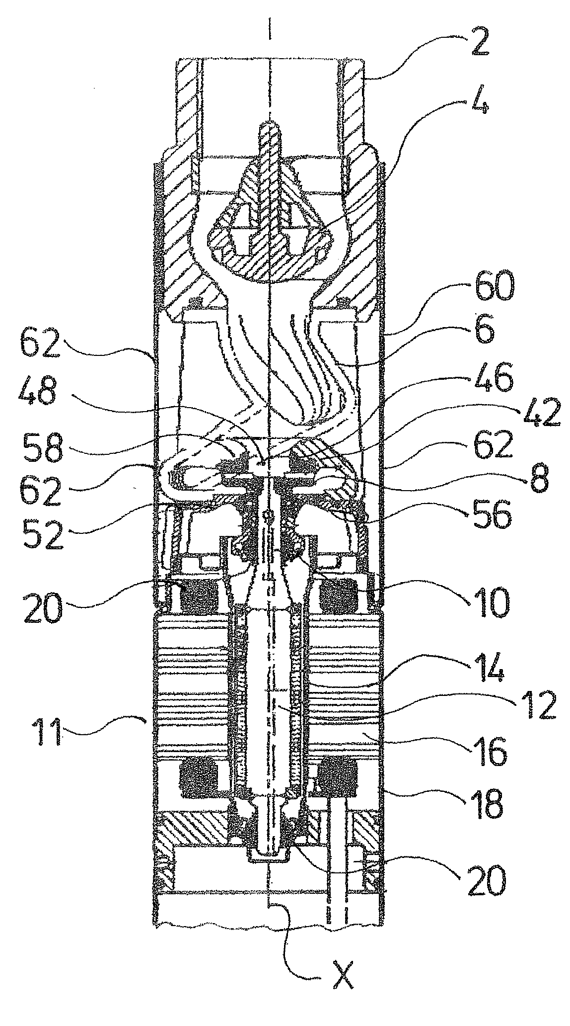
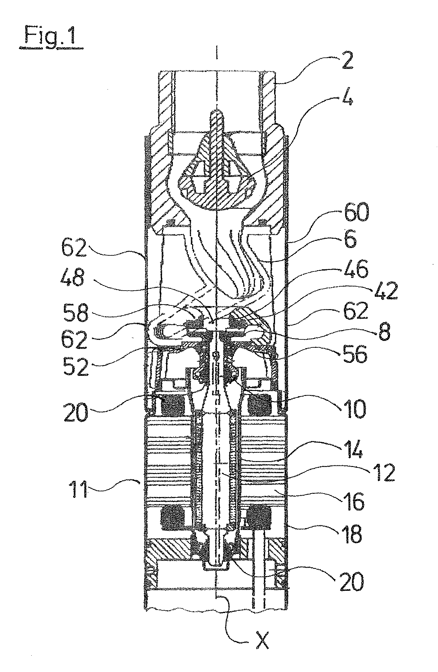
[0041]FIG. 1 shows a sectional view of the upper end of a submersible pump. The lower end, in which the electronics for the control and regulation of the pump are accommodated, is not shown in the Figure. The pump assembly at its upper end comprises a connection stub 2 with a return valve 4 arranged therein. A spiral housing 6, which surrounds the impeller 8, connects upstream to the connection stub 2, inside the pump assembly. The impeller 8 is arranged at the axial end of the single-piece rotor shaft 10 of the electric motor 11, or its permanent magnet rotor 12. The impeller 8 is firmly fixed on the rotor shaft 10, in particular is also firmly connected in the axial direction X. The permanent magnet rotor 12 runs inside a can 14, which is annularly surrounded by the stator 16 on its outer periphery. The stator 16 is designed in a known manner as a lamination bundle with coils windings. The stator 16, as a whole, is hermetically encapsulated in a stator housing 18. The rotor shaft ...
PUM
 Abstract
Description
Claims
Application Information
 - R&D
- Intellectual Property
- Life Sciences
- Materials
- Tech Scout
- Unparalleled Data Quality
- Higher Quality Content
- 60% Fewer Hallucinations
Browse by: Latest US Patents, China's latest patents, Technical Efficacy Thesaurus, Application Domain, Technology Topic, Popular Technical Reports.
© 2025 PatSnap. All rights reserved.Legal|Privacy policy|Modern Slavery Act Transparency Statement|Sitemap|About US| Contact US: help@patsnap.com


