
Cochlear Implant Pitch Intensity

Active Publication Date: 2009-01-08
MED EL ELEKTROMEDIZINISCHE GERAETE GMBH
View PDF8 Cites 15 Cited by
  • Summary
  • Abstract
  • Description
  • Claims
  • Application Information

AI Technical Summary

Problems solved by technology

The phase duration cannot be chosen arbitrarily short, because the shorter the pulses, the higher the current amplitudes have to be to elicit action potentials in neurons, and current amplitudes are limited for various practical reasons.

Method used


Image

  • Cochlear Implant Pitch Intensity
  • Cochlear Implant Pitch Intensity
  • Cochlear Implant Pitch Intensity

Examples


Embodiment Construction

[0021]Most pitch perception studies to date have focused on the influence of position and rate based mainly on relatively short electrode arrays using bipolar stimulation. See Collins L M, Zwolan T A, Wakefield G H, Comparison Of Electrode Discrimination, Pitch Ranking, And Pitch Scaling Data In Postlingually Deafened Adult Cochlear Implant Subjects, J. Acoust. Soc. Am. 1997; 101:440-455, which is incorporated herein by reference. But little attention has been given to the sensation of pitch in deeply inserted electrodes or the influence of stimulation intensity level on pitch perception. See Cohen L T, Busby P A, Whitford L A, et al., Cochlear Implant Place Psychophysics—Pitch Estimation With Deeply Inserted Electrodes, Audiol. Neurootol. 1996; 1:265-277, which is incorporated herein by reference.

[0022]This is rather surprising since the effect of acoustic stimulus intensity on perceived pitch was first reported over seven decades ago. See, Stevens S S, The Relation Of Pitch To Int...


PUM


Abstract

A system and method are described for generating electrode stimulation signals for an implanted electrode array having multiple stimulation electrodes. An acoustic audio signal is processed to determine associated pitch characteristics and frequency component information. From the pitch characteristics and the frequency component information, electrode stimulation signals are determined which have intensity levels that reflect the pitch characteristics. Then audio nerve tissue is stimulated by applying the electrode stimulation signals to the electrodes in the implanted electrode array.

Description

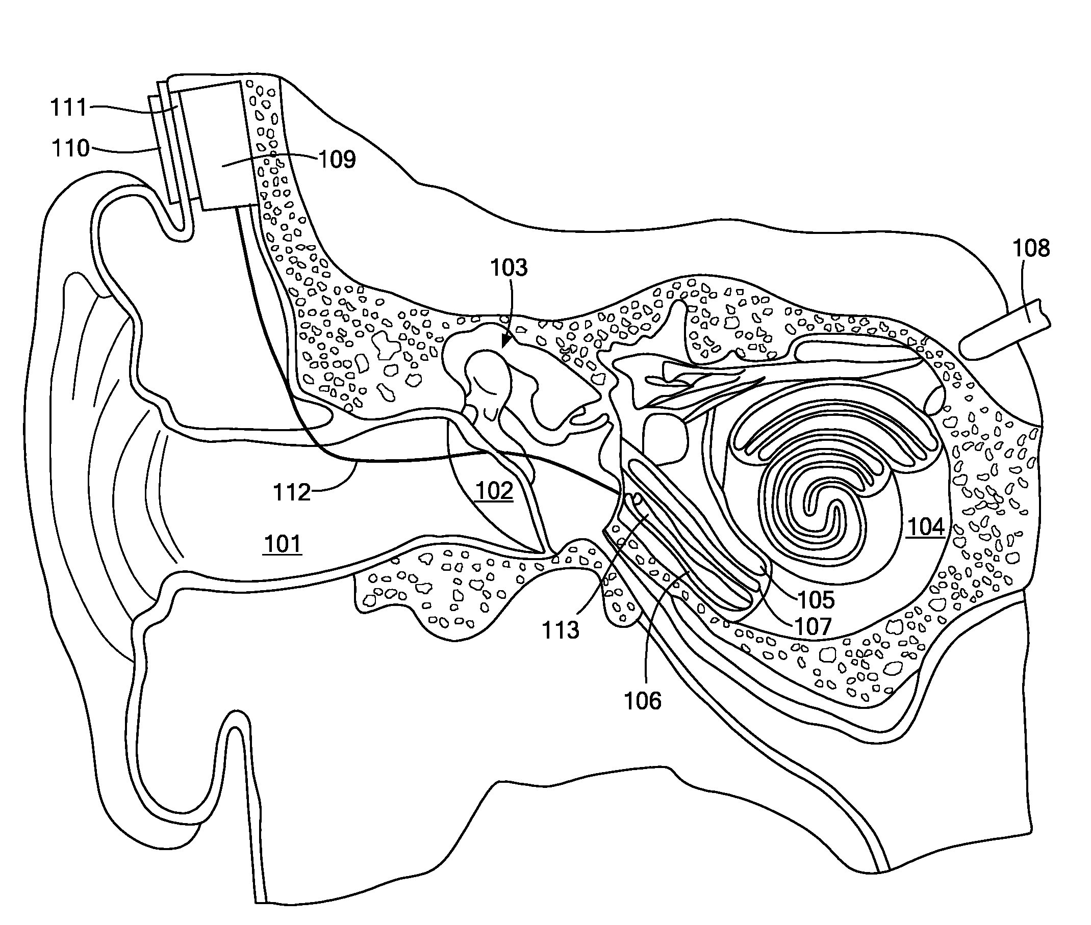
[0001]This application claims priority from U.S. Provisional Patent Application 60 / 947,727, filed Jul. 3, 2007, which is incorporated herein by reference.FIELD OF THE INVENTION[0002]The present invention relates to audio prostheses, and specifically to the signal processing used therein.BACKGROUND ART[0003]FIG. 1 shows a section view of an ear with a typical cochlear implant system. A normal ear transmits sounds through the outer ear 101 to the eardrum 102, which moves the bones of the middle ear 103, which in turn excites the cochlea 104. The cochlea 104 includes an upper channel scala vestibuli 105 and a lower channel scala tympani 106 which are connected by the cochlear duct 107. In response to received sounds transmitted by the middle ear 103, the fluid-filled scala vestibuli 105 and scala tympani 106 transmit fluid waves, functioning as an acoustic transducer to generate electric pulses that are transmitted to the cochlear nerve 108, and ultimately to the brain.[0004]To overcom...

Claims


Application Information

Patent Timeline
IPC IPC(8): A61F11/00
CPCA61N1/36032A61N1/0541A61N1/36038A61N1/36039
Inventor ARNOLDNER, CHRISTOPHHAMZAVI, JAFAR SASAN
Owner MED EL ELEKTROMEDIZINISCHE GERAETE GMBH
Learn More