Slotwall mounting assembly

a technology for mounting brackets and slotwalls, which is applied to show shelves, domestic applications, and hangers, etc., can solve the problems of multiple parts and assembly, difficult to handle, and easy to be dislodged from the slotwall after installation, so as to improve the flexibility of the locking flange, reduce the effort, and adapt to existing slotwall accessories.

Inactive Publication Date: 2009-01-15
WINDQUEST
View PDF17 Cites 68 Cited by
  • Summary
  • Abstract
  • Description
  • Claims
  • Application Information

AI Technical Summary

Benefits of technology

[0016]In one embodiment, the slotwall mounting bracket includes a generally planar body, an upper L-shaped mounting flange, and a lower locking flange. The mounting flange extends from the body and hooks into a first slotwall groove, supporting the mounting bracket on the upper surface of a horizontal rail on the slotwall. The locking flange extends from the body and snap-fits over the lip extending downwardly at the bottom surface of the horizontal rail, preventing the mounting bracket from inadvertently rotating upward and off from the slotwall.
[0017]In a more specific embodiment, the locking flange includes a first portion, a second portion, and a third portion. The first portion extends generally perpendicularly from the body. The second portion extends at an angle upwardly from the first portion such that the second portion fits around the downwardly extending lip to hold the mounting bracket on the slotwall. The third portion extends from the second portion to provide a ramp at the leading edge of the locking flange to lever the locking flange over the lip and lock over the lip in snap-fit engagement. One or more of the portions may define one or more voids to increase the flexibility of the locking flange relative to the body and reduce the effort required to snap fit the locking flange about the lip. The cutout also provides a pry point to aid in removal of the mounting bracket from the slotwall.
[0018]In a further embodiment, the body of the mounting bracket includes a rear surface facing the slotwall and a front surface opposite the rear surface. The front surface includes one or more protrusions that provide a surface for welding an accessory mount to the mounting bracket. The accessory mount enables a variety of conventional accessories to be attached to and supported by the mounting bracket, avoiding the purchase or remanufacturing of modified slotwall accessories, making the present invention easily adaptable to existing slotwall accessories.

Problems solved by technology

The major disadvantage of conventional slotwall mounting brackets is how easy they can be dislodged from the slotwall after installation.
A major disadvantage associated with both embodiments disclosed in the 753 patent is that multiple parts and assembly are required.
The increase number of parts, the manual assembly of the components, and the two handed operation for installing and removing the brackets makes them more expensive to manufacture, more difficult to handle.
There has been a long felt vet unresolved need to a slotwall mounting bracket that can be easily attached to a slotwall rail using a single hand yet once attached is not easily dislodged by a casually applied upward force commonly associated with passers-by.

Method used


Image

  • Slotwall mounting assembly
  • Slotwall mounting assembly
  • Slotwall mounting assembly

Examples


Embodiment Construction

[0032]For purposes of the following description, the terms “upper,”“lower,”“left,”“rear,”“front,”“vertical,”“horizontal” and derivatives of such terms shall relate to the invention as oriented in FIG. 12. However, it is to be understood that the invention may assume various alternative orientations and configuration, except where expressly specified to the contrary. It is also to be understood that the devices and processes illustrated in the attached drawings, and described in the following specification are simply exemplary embodiments of the inventive concepts defined in the inventive concepts of this invention. Specific dimensions and other physical characteristics relating to the embodiments disclosed herein are not to be considered as limiting unless expressly stated otherwise.

[0033]I. Overview

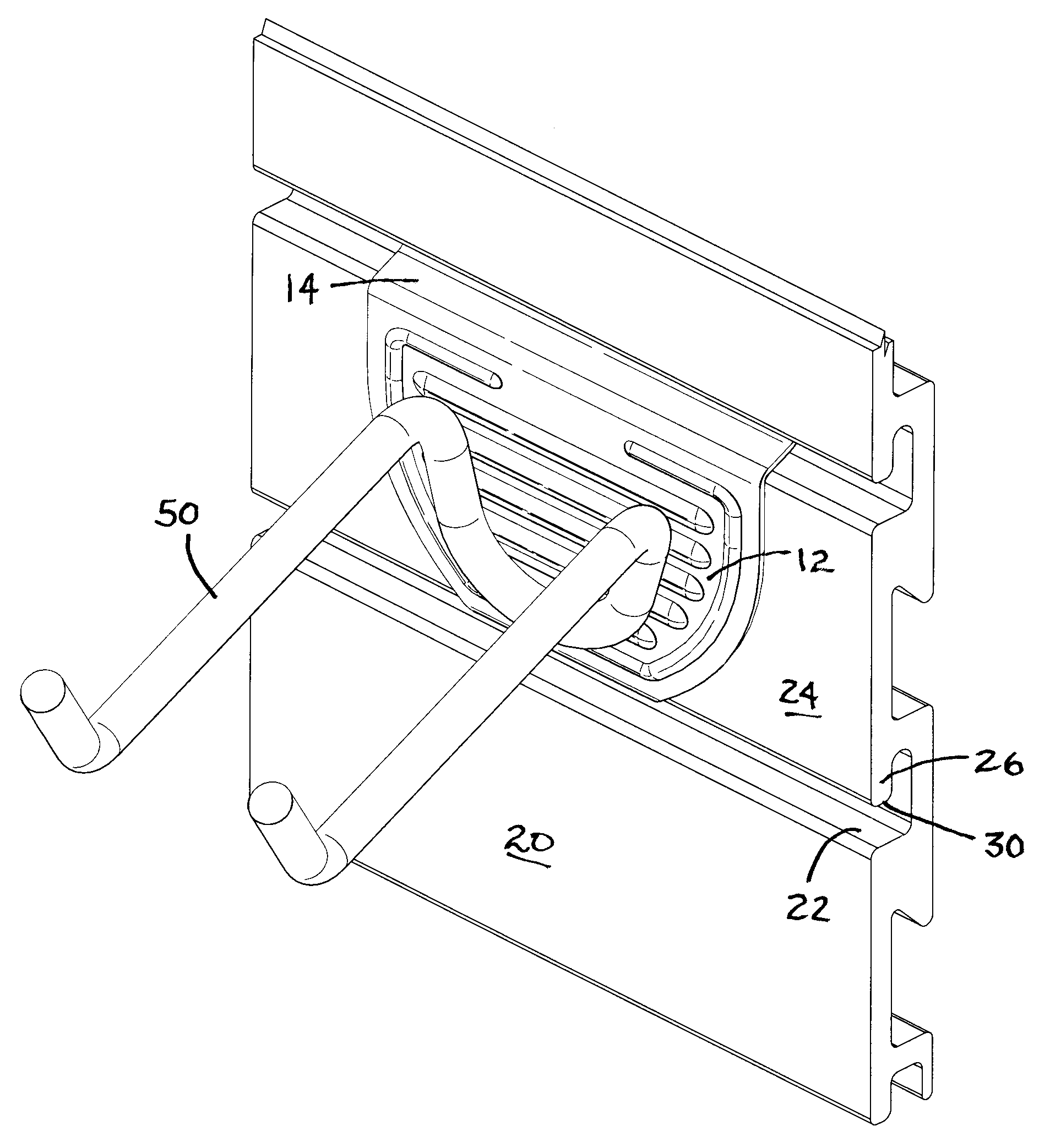
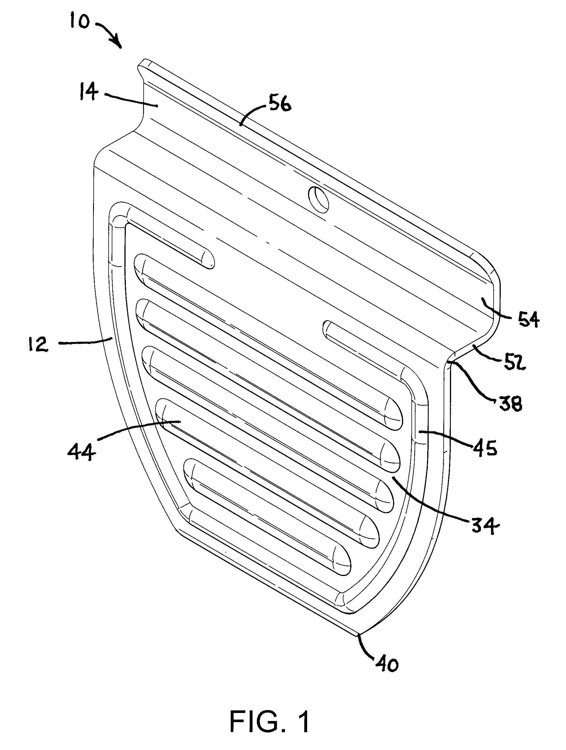
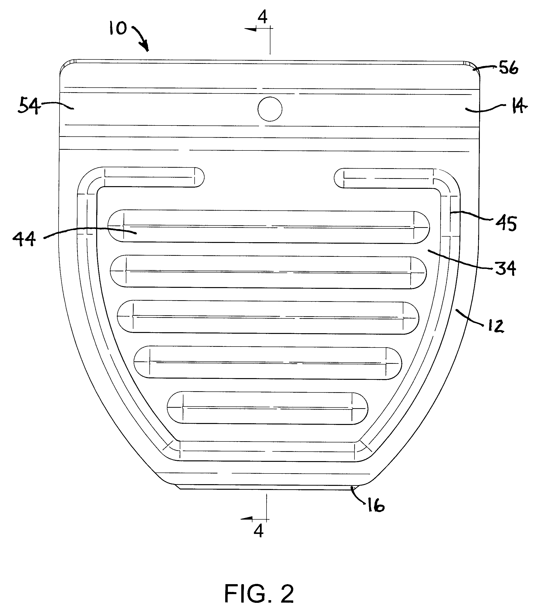
[0034]A slotwall mounting bracket in accordance with a preferred embodiment of the present invention is shown in FIGS. 1 and 3 generally designated 10. The mounting bracket includes a ge...


PUM


Abstract

An assembly for hanging items from a wall is provided having a plurality of parallel and equidistantly spaced rails, each having a first and a second opposing edge and one or more of which define a lip. One or more mounting brackets are provided for attaching to the rails. Each mounting bracket includes a base plate, and a mounting flange and a locking flange extending from the base plate. The mounting flange engages and is retained on the first edge of a rail and extends behind a lip of an adjacent rail. The locking flange is wedged over the lip of the mounting rail and held tightly in place by the snap-fit engagement of the locking flange over the lip.

Description

CROSS REFERENCE TO RELATED APPLICATION[0001]This is a continuation-in-part patent application pursuant to 37 C.F.R. 1.53(b) claiming priority to U.S. non-provisional patent application Ser. No. 11 / 135,942 filed May 24, 2005, now, abandoned.BACKGROUND OF THE INVENTION[0002]1. Field of the Invention[0003]The present invention relates generally to mounting fixtures and more particularly to a slotwall mounting assembly having a number of vertically spaced, elongated, horizontally extending rails that define slots or channels between the rails adapted to receive one or more mounting brackets. Walls made from such rails are generally known or referred to as “slotwalls.”[0004]2. Description of the Related Art[0005]Slotwalls are used in a wide variety of applications for storing and displaying products, tools, and accessories. Examples of the industries in which slotwalls are used include retail display, closet storage, garage storage, and office furniture. As is well known, a slotwall is a...

Claims


Application Information

Patent Timeline
Patent Type & Authority Applications(United States)
IPC IPC(8): A47F5/08
CPCA47F5/0846
Inventor TALLMAN, RANDALL E.
Owner WINDQUEST
Why Eureka
Try Eureka