Radio Frequency Identification System and Data Reading Method

a radio frequency identification and data reading technology, applied in the field of radio frequency identification (rfid) systems and encoding and decoding methods, can solve the problems of difficult and expensive implementation, phase information too sensitive to be relied on, and inability to encode information by using phase and polarization

Inactive Publication Date: 2009-01-15
INKSURE RF
View PDF10 Cites 35 Cited by
  • Summary
  • Abstract
  • Description
  • Claims
  • Application Information

AI Technical Summary

Benefits of technology

[0052]According to yet another embodiment of the invention, the processing of the re-radiate...

Problems solved by technology

It should be noted that encoding tags with information by using phase and polarization can be impractical and expensive.
Thus, it appears that phase information is too sensitive to be relied on.
Such methods can provide characterization of the illuminated tags, bu...

Method used


Image

  • Radio Frequency Identification System and Data Reading Method
  • Radio Frequency Identification System and Data Reading Method
  • Radio Frequency Identification System and Data Reading Method

Examples


Embodiment Construction

[0095]The principles and operation of the radio frequency identification system and data reading method according to the present invention may be better understood with reference to drawings and the accompanying description. It should be understood that these drawings which are not necessarily to scale, and examples in the description, are given for illustrative purpose only and are not intended to limit the scope of the invention. The same reference numerals will be utilized for identifying those components, which are common in the multi-bit data carriers shown in the drawings throughout the present description of the invention. Examples of constructions, materials, dimensions, and manufacturing processes are provided for selected elements. Those versed in the art should appreciate that many of the examples provided have suitable alternatives which may be utilized.

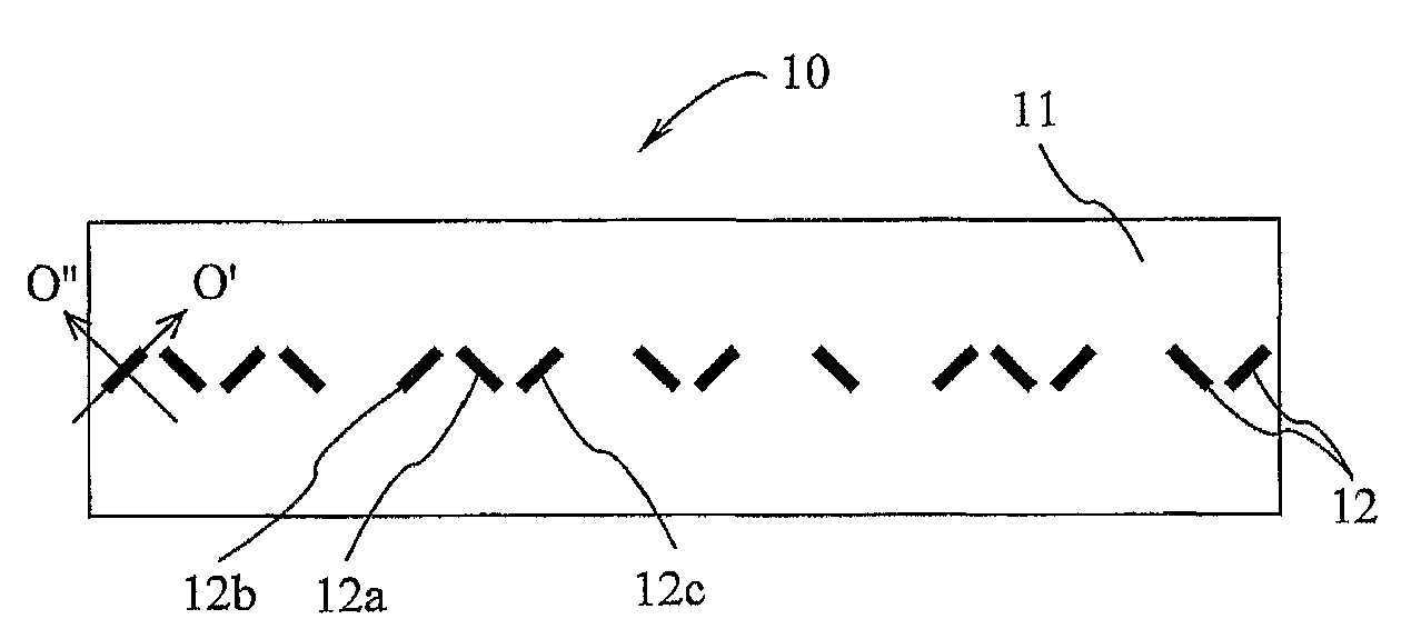
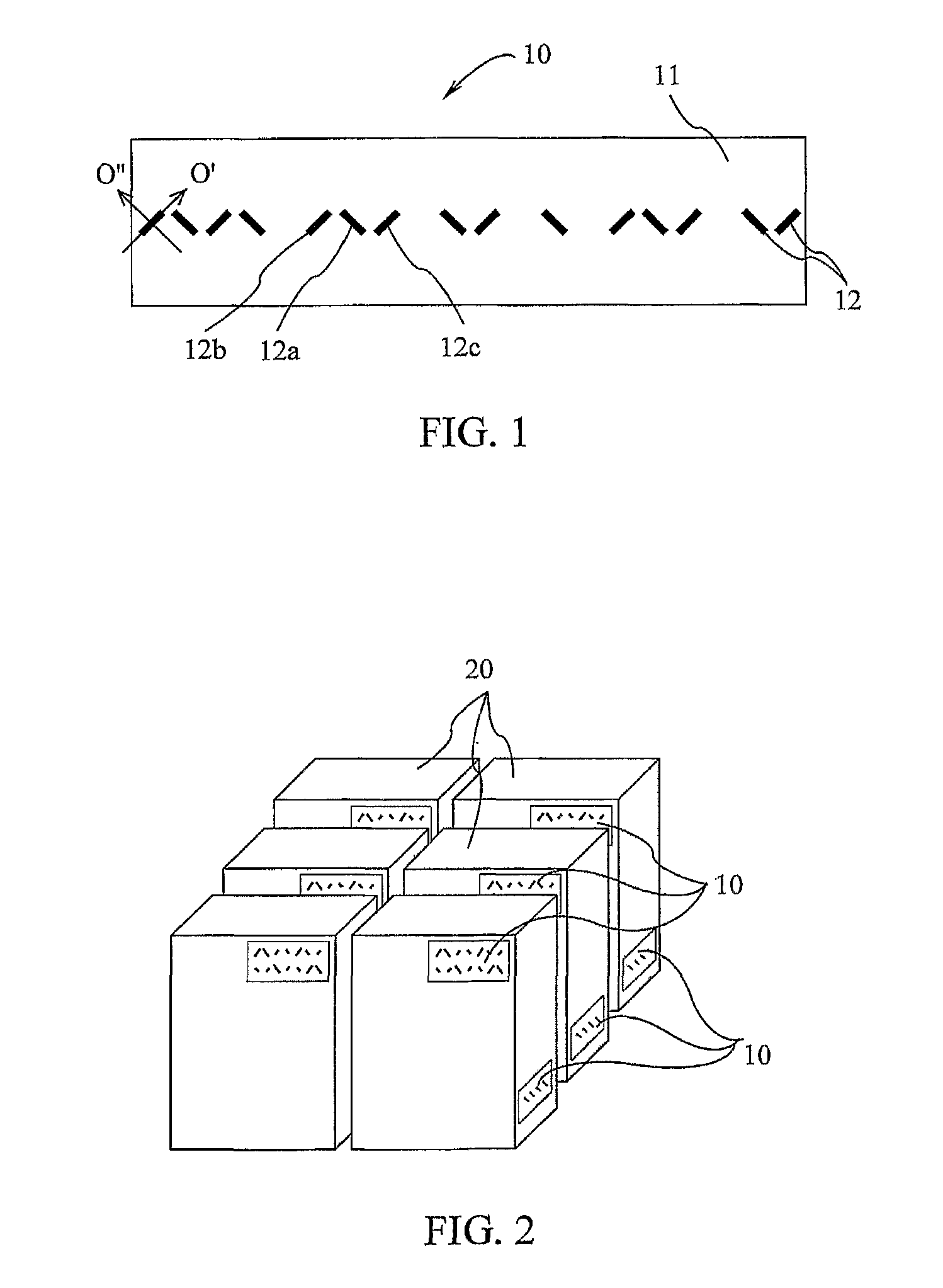
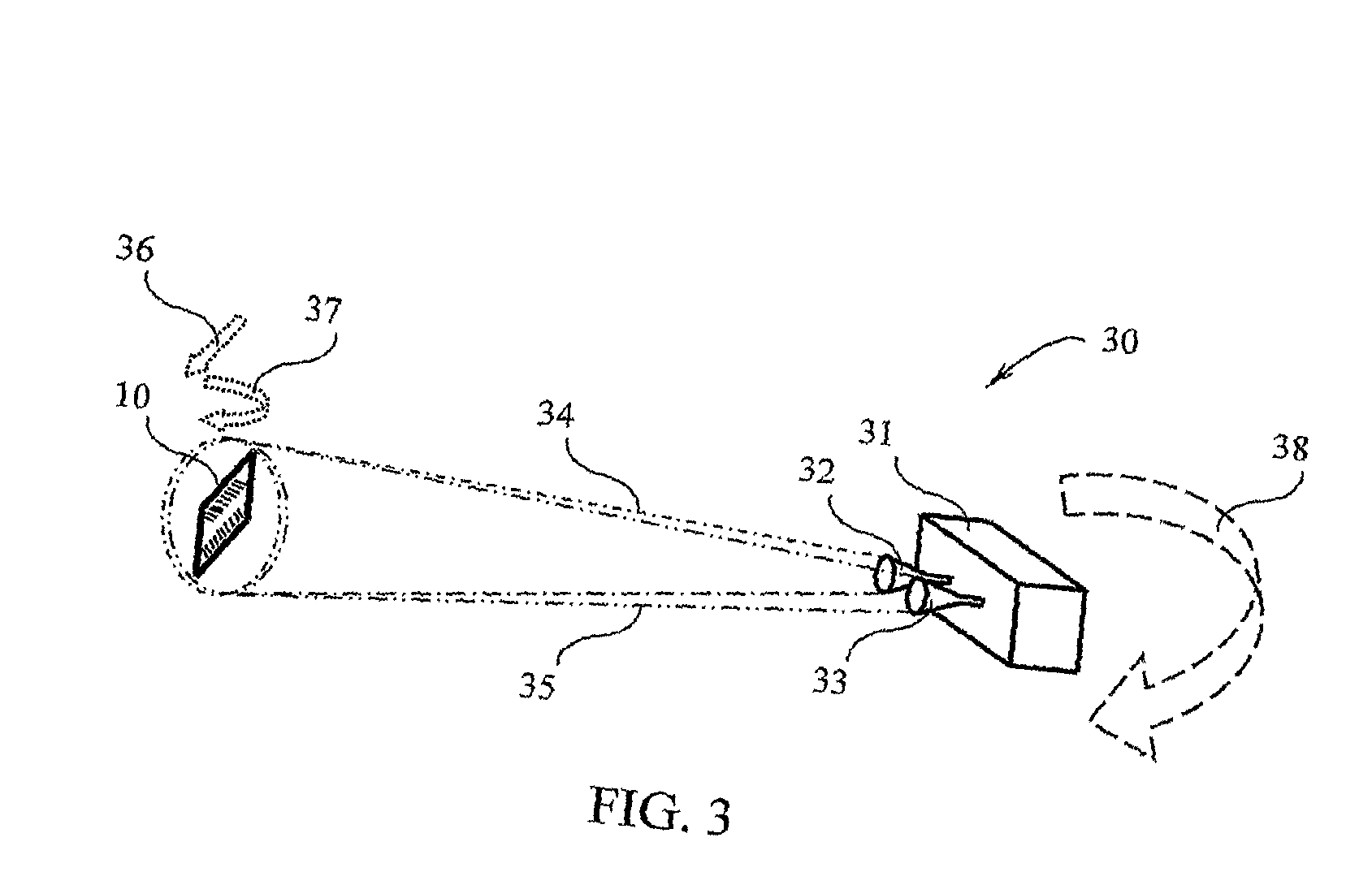
[0096]The present invention describes a novel chipless RFID data tag that can be target interrogated and read by a rada...


PUM


Abstract

A system and method for reading an RFID data tag comprising a plurality of diffractive elements being indicative of machine-readable data carried by the tag are provided. The diffractive elements have such shape that the dimension of the diffractive elements along one axis is substantially different than the dimension of the elements along the perpendicular axis. Each diffractive element is oriented in a direction other than the direction of its neighboring elements. The system comprises a transmitting antenna configured for emitting an RF radiation signal at a predetermined polarization towards the tag; and a receiving antenna configured for collecting re-radiated RF radiation produced by the tag in response to the RF radiation signal at a polarization orthogonal to the polarization of the transmitting antenna and generating electromagnetic signals indicative of the data carried by the tag. The system also includes an interrogator unit configured for generating the transmitted RF radiation signal and processing the electromagnetic signals produced by the receiving antenna for determining the data carried by the tag.

Description

RELATED APPLICATIONS[0001]This application is a Continuation of PCT application serial number PCT / IL2007 / 000022, filed on Jan. 9, 2007, and claims the benefit under 35 USC 119(e) of U.S. Provisional Application No. 60 / 780,307, filed on Mar. 9, 2006, both of which are incorporated herein by reference in their entirety.FIELD OF THE INVENTION[0002]This invention relates to radio frequency identification (RFID) systems and encoding and decoding methods, and in particular, to a data tag or label used in an identification system.BACKGROUND OF THE INVENTION[0003]Radio Frequency Identification (RFID) is an automatic identification technology, relying on storing and remotely retrieving data, using devices called RFID tags or transponders. The RFID system consists of two major components—an interrogator / reader and a data carrier, such as a data tag or data label. These components work together to provide the end user with a non-contact solution to uniquely identify people, animals or objects....

Claims


Application Information

Patent Timeline
IPC IPC(8): G06K19/06G06K7/00
CPCG06K19/06037G06K7/143G01S13/751G01S13/9076
Inventor KOFMAN, SEMIONMEERFELD, YARONSANDLER, MAYADUKLER, SHLOMOALCHANATIS, VICTOR
Owner INKSURE RF
Why Eureka
Try Eureka