Media separating and feeding device and media processing device

a technology of feeding device and media processing device, which is applied in the direction of article separation, thin material processing, transportation and packaging, etc., can solve the problems of inefficient cost and space, inability to provide a dedicated drive motor, so as to reduce the size of the device, and reduce the cost. , the effect of low cost drive mechanism

Active Publication Date: 2009-01-15
SEIKO EPSON CORP
View PDF8 Cites 15 Cited by
  • Summary
  • Abstract
  • Description
  • Claims
  • Application Information

AI Technical Summary

Benefits of technology

[0019]The media separating and feeding mechanism according to at least one embodiment of the present invention uses a single drive motor to drive a pressure member, a feed roller, and a separation roller. A small, low cost drive mechanism can thus be achieved.
[0020]The drive power transfer mechanism of at least one embodiment of the invention uses a one-way clutch mechanism. The one-way clutch mechanism can be assembled coaxially to a gear used in the drive power transfer mechanism. The drive power transfer path can also be switched by simply changing the direction of drive motor rotation. Because the drive power transfer mechanism can thus be rendered small and compact, little installation space is required and device size can be reduced.
[0021]Furthermore, by using a one-way clutch to prevent the rollers from turning in reverse, the rollers will not cause the sheet media to move in the reverse direction out of the media insertion unit, and can therefore be prevented from falling out of the media insertion unit.
[0022]Other objects and attainments together with a fuller understanding of at least one embodiment of the invention will become apparent and appreciated by referring to the following description and claims taken in conjunction with the accompanying drawings.

Problems solved by technology

Providing a dedicated drive motor as the drive power source for a pressure member that is moved only at the beginning and end of the check processing operation is not space efficient.
Providing a dedicated drive motor is thus inefficient in terms of cost as well as space.

Method used


Image

  • Media separating and feeding device and media processing device
  • Media separating and feeding device and media processing device
  • Media separating and feeding device and media processing device

Examples


Embodiment Construction

[0034]A preferred embodiment of a check processing device having the media separating and feeding device according to at least one embodiment of the present invention is described below with reference to the accompanying figures.

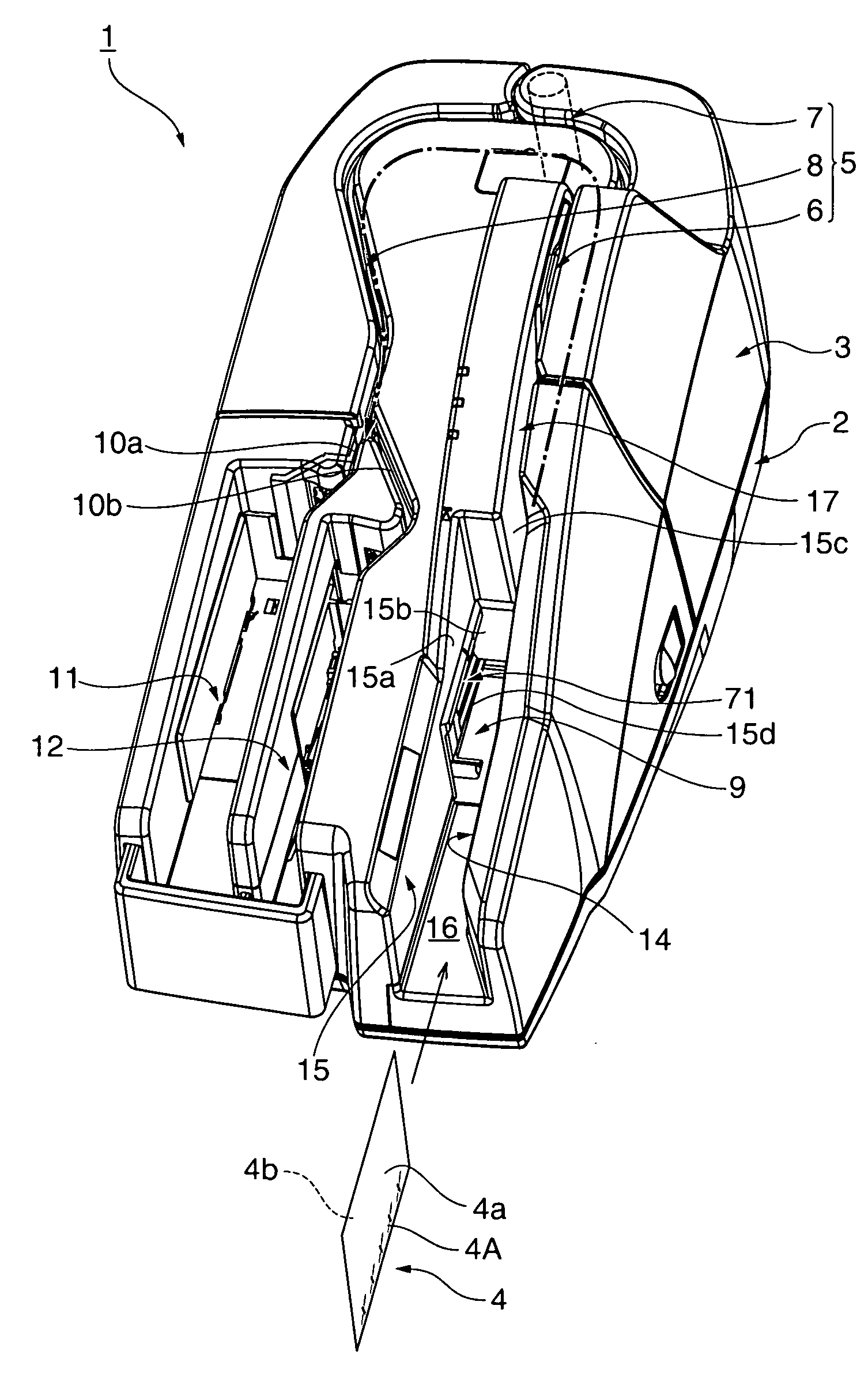
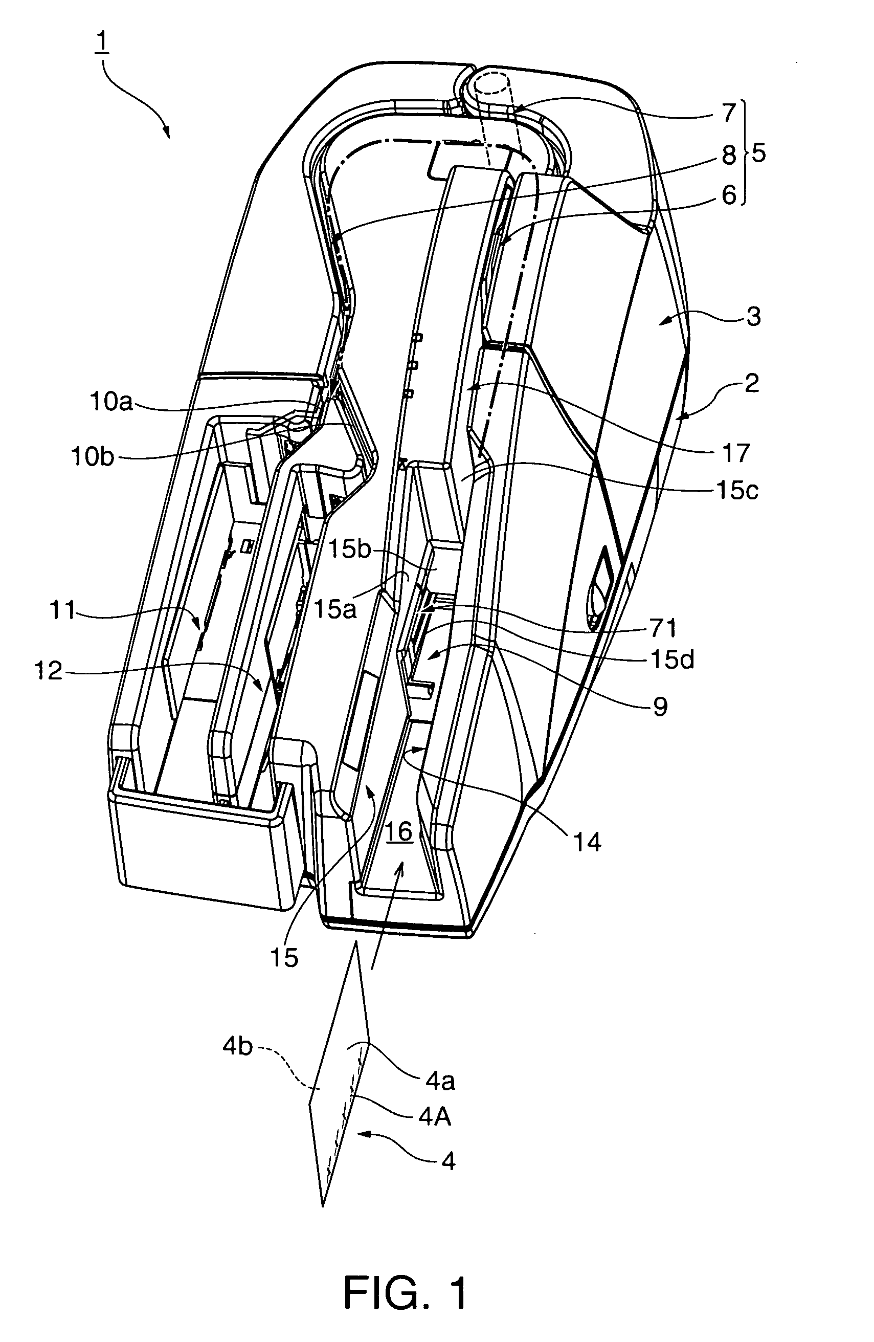
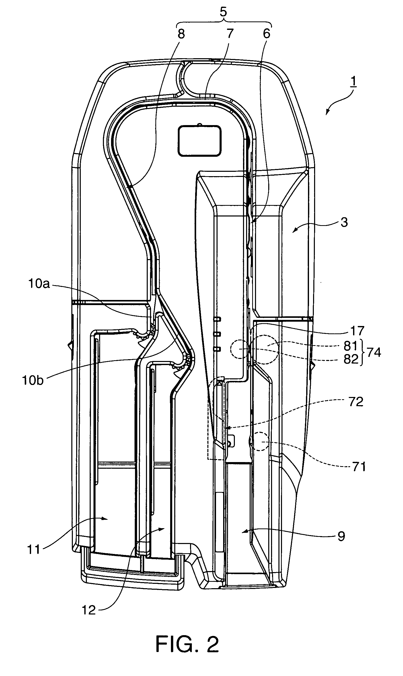
[0035]FIG. 1 is an external oblique view of a check processing device 1 according to at least one embodiment of the invention, and FIG. 2 is a plan view of the same. This check processing device 1 has a bottom case 2 and a top case 3 that covers the top of the bottom case 2, and various parts and assemblies are disposed inside the cases. A check transportation path 5 for conveying checks 4 (sheet media) is formed in the top case 3.

[0036]The check transportation path 5 is a narrow vertical slot that curves in a basically U-shaped configuration when seen from above, and includes a straight upstream-side transportation path portion 6, a curved transportation path portion 7 that continues from the upstream-side transportation path portion 6, and a slightly curvi...


PUM

PropertyMeasurementUnit
angleaaaaaaaaaa
pressureaaaaaaaaaa
torqueaaaaaaaaaa

Abstract

A mechanism enables efficiently reducing the size of a check feeding device for separating and feeding checks one at a time. The check separating and feeding mechanism 13 uses a single drive motor 85 to drive the feed roller 71, pressure member 72, and separation roller 81. When the drive motor 85 turns in a second direction, torque is transferred through a second one-way clutch mechanism 88f to both rollers 71 and 81, and the check 4 separating and feeding operation begins. When the drive motor 85 turns in this direction, the first one-way clutch mechanism 88e disengages the drive motor 85 from the drive power transfer path to the pressure member 72, and a tension spring 99 pulls the pressure member 72 in the direction pressing the checks 4 to the feed roller 71. When the drive motor 85 turns in an opposite first direction, the torque of the drive motor 85 returns the pressure member 72 to the standby position, drive power is not transferred to the rollers 71 and 81, and the rollers do not turn.

Description

BACKGROUND OF THE INVENTION[0001]1. Field of Invention[0002]The present invention relates to a media separating and feeding device that separates and feeds checks, printing paper, and other types of sheet media one at a time. The invention also relates to a check processing device, a printer, a scanner, a magnetic reader, or other type of media processing device that incorporates the media separating and feeding device.[0003]2. Description of Related Art[0004]Banks and other financial institutions use check processing devices (also called check readers) to image and read magnetic ink characters from checks, promissory notes, and other check-like negotiable instruments, and to sort the checks based on the acquired information. As electronic check processing has become more common in recent years, the scanned image data and magnetic ink character data is also processed and managed using computers. See, for example, the check reader taught in Japanese Unexamined Patent Appl. Pub. JP-A-...

Claims


Application Information

Patent Timeline
Patent Type & Authority Applications(United States)
IPC IPC(8): B65H5/06
CPCB65H1/025B65H3/0653B65H2701/1912B65H2301/3122B65H3/5246
Inventor SASAKI, TOSHIYUKI
Owner SEIKO EPSON CORP
Why Eureka
Try Eureka