
Pipe Fitting Wireform for Measuring Linear Distance and Method

a technology for pipe fittings and wireforms, applied in the direction of hose connections, apertured gauges, instruments, etc., can solve the problems of difficulty for a man working alone to make the center-to-end or end-to-center measuremen

Inactive Publication Date: 2009-01-15
LONG FREDRICK D
View PDF17 Cites 11 Cited by
  • Summary
  • Abstract
  • Description
  • Claims
  • Application Information

AI Technical Summary

Benefits of technology

[0021]FIG. 9 is photograph showing a workman meas...

Problems solved by technology

Particularly in field installations, it is difficult for a man working by himself to make the center-to-end or end-to-center measurement between the fittings on the pipes to be joined.

Method used


Image

  • Pipe Fitting Wireform for Measuring Linear Distance and Method
  • Pipe Fitting Wireform for Measuring Linear Distance and Method
  • Pipe Fitting Wireform for Measuring Linear Distance and Method

Examples


Embodiment Construction

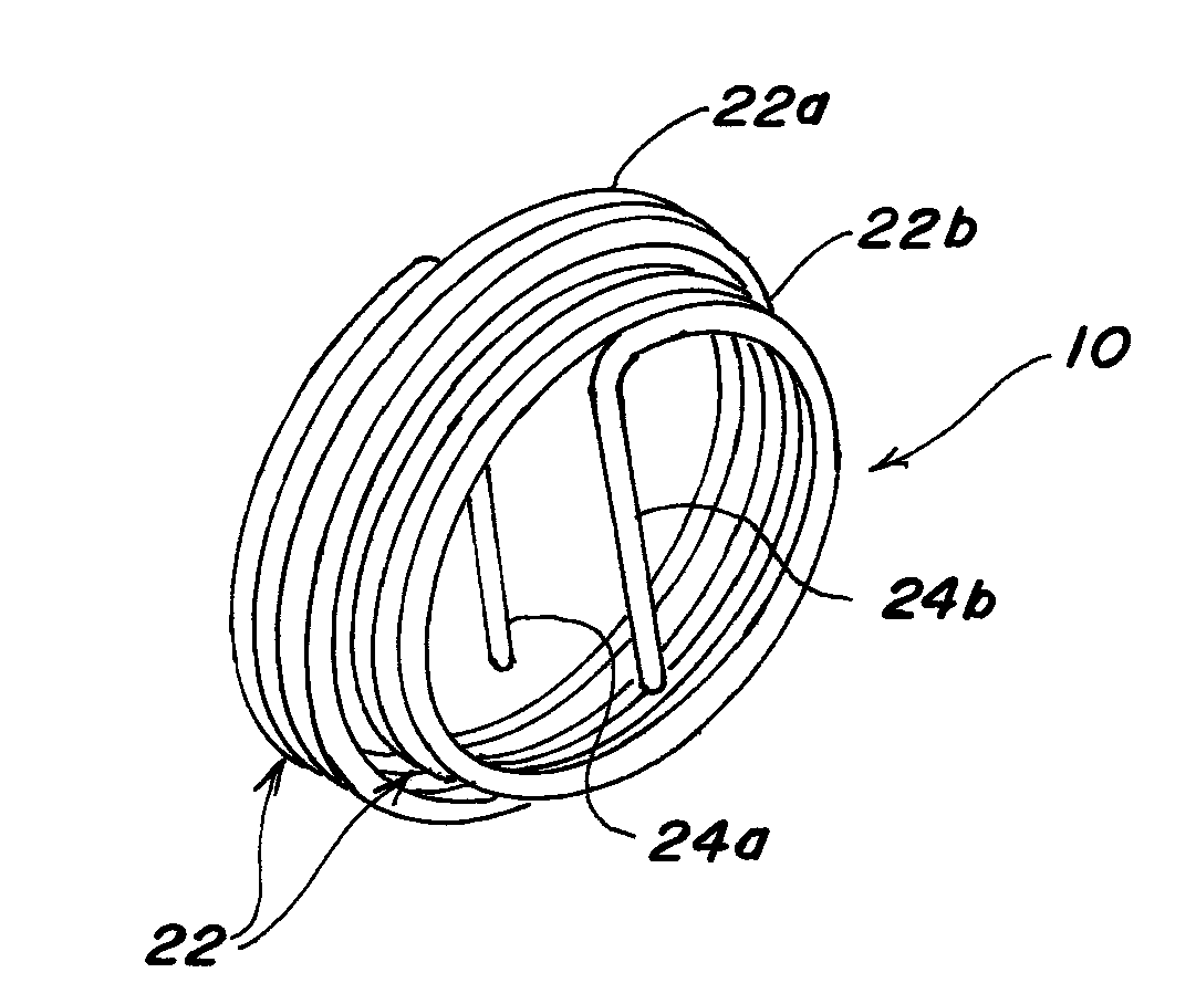
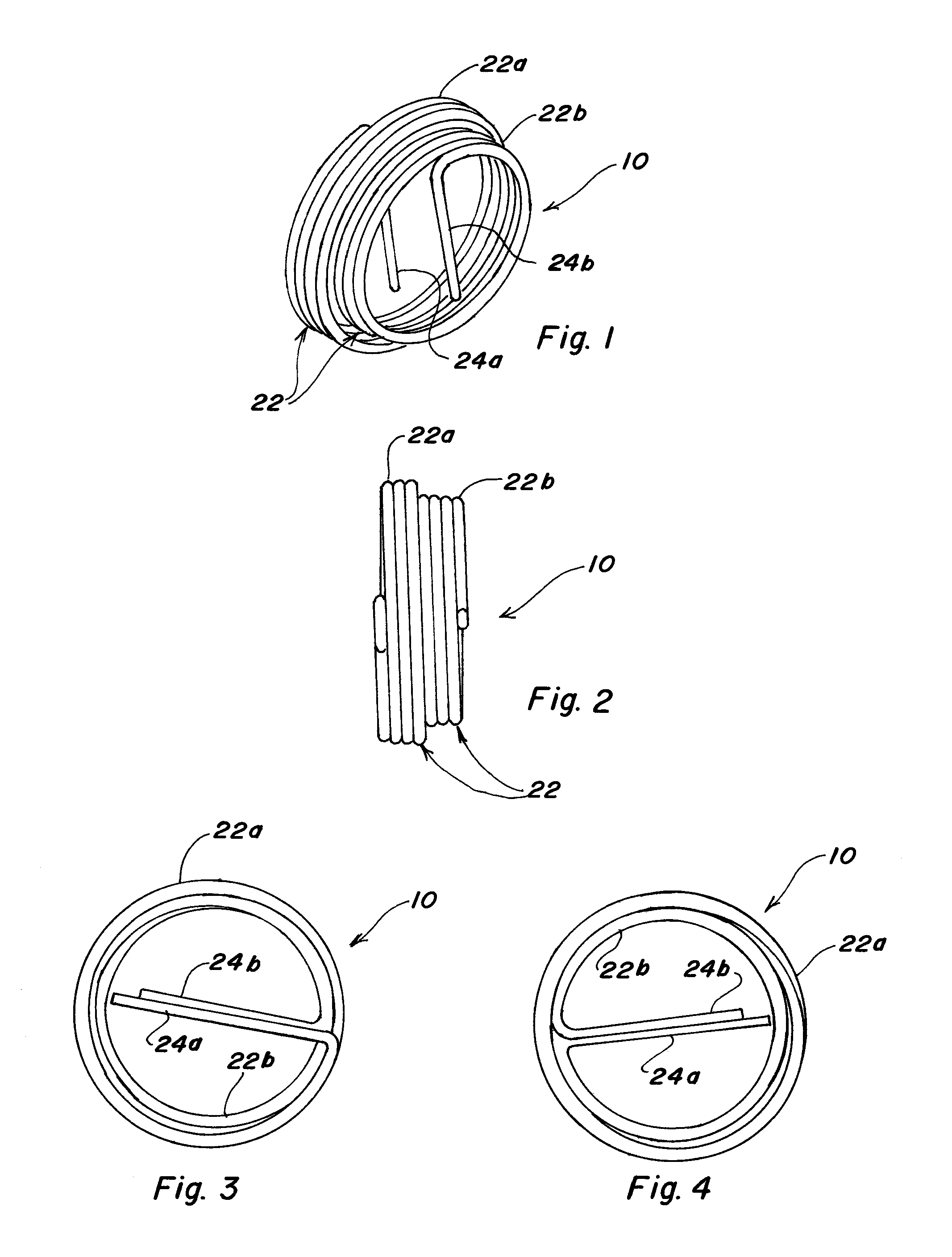
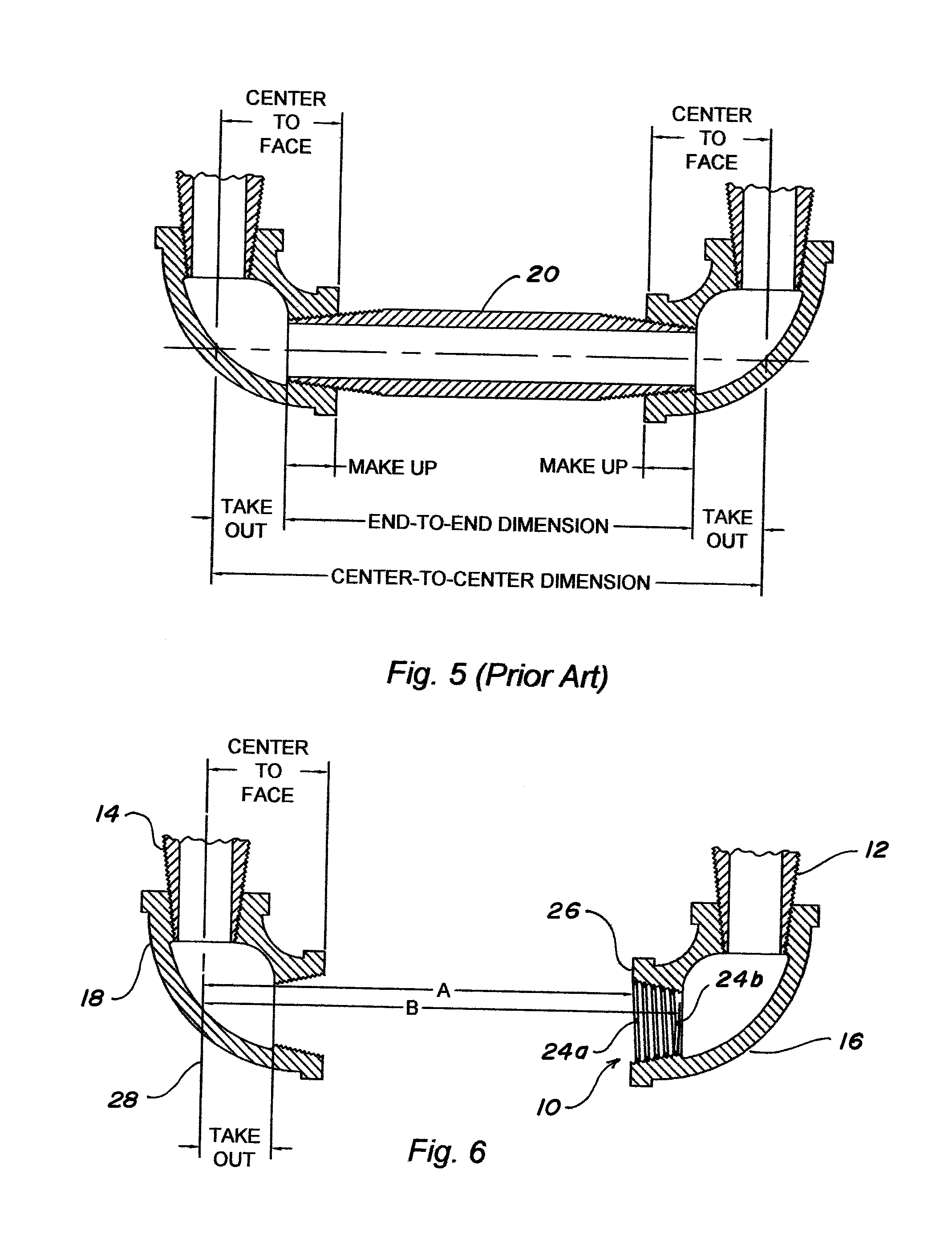
[0023]Referring to the drawings more particularly by reference character, reference numeral 10 refers to a pipe fitting wireform in accordance with the present invention. For use in joining a first pipe-to-be-joined 12 with a second pipe-to-be-joined 14 as illustrated in FIG. 6, a first screw threaded fitting 16 may be temporarily attached to first pipe-to-be-joined 12 and a second screw threaded fitting 18 may be attached to second pipe-to-be-joined 14. Pipe fitting wireform 10 may then be used to determined an end-to-end length of a third pipe 20 (FIG. 5) which is cut and threaded to connect first and second pipes-to-be-joined 12, 14 through first and second fittings 16, 18.

[0024]As seen in FIGS. 1-4, pipe fitting wireform 10 is a coil 22 of spring steel having an outside diameter substantially equal to the nominal size of one of said pipe fittings 16, 18, for example fitting 16. The coils of pipe fitting wireform 10 have substantially the same number of turns per inch as pipe fit...


PUM


Abstract

A pipe fitting wireform which when threaded into a fitting allows a user to measure center-to-end or end-to-center of the fitting to determine the length of a pipe needed to connect a pair of pipe fittings in a pipe assembly. The fitting wireform is a coil with a free end bent laterally to form a tang. The fitting wireform having an outside diameter substantially equal to the nominal size of the pipe fitting with substantially the same number of turns per inch as the pipe fitting such that the pipe fitting wireform can be threaded into the pipe fitting.

Description

BACKGROUND OF THE INVENTION[0001]1. Field of the Invention[0002]The present invention relates to a pipe fitting wireform for field or shop application for measuring the center-to-end or end-to-center of a fitting to determine the end-to-end length of a pipe needed to connect a pair of pipe fittings in a pipe assembly.[0003]2. Brief Description of the Prior Art[0004]Dimensions on pipe drawings specify the center lines and / or points on center lines; they do not specify pipe lengths. This system of distance dimensioning and measurement is also followed in the fabrication and installation of pipe assemblies.[0005]To determine actual pipe length, allowances must be made for the length of the fittings and the distance the pipe-to-be-cut will be threaded into the fitting. The method of doing this is to subtract an amount called the take-out from the center-to-center dimension. The relationships of the take-out to other threaded pipe connection distances, termed make-up, center-to-center an...

Claims


Application Information

Patent Timeline
IPC IPC(8): F16L55/00G06F19/00
CPCG01B3/34
Inventor LONG, FREDRICK D.
Owner LONG FREDRICK D
Learn More