
Seating unit with formed cushion, and manufacturing method

a seating unit and cushion technology, applied in the field of seating units, can solve the problems of affecting the quality of the seat cushion, the cushion is often distorted, and the upholstery is not uniform after assembly, so as to reduce the distortion and objectionable wrinkles, minimize the balance tension, and minimize the effect of tension

Active Publication Date: 2009-01-15
STEELCASE INC
View PDF22 Cites 2 Cited by
  • Summary
  • Abstract
  • Description
  • Claims
  • Application Information

AI Technical Summary

Benefits of technology

The present invention provides methods and components for upholstering furniture and seating units. The invention involves using a cushion made of formable polymeric fibers that can be shaped and molded to fit the contour of the furniture or seating unit. The cushion is then covered with an upholstery cover that can be positioned and secured in place. The invention also includes methods for stress-relieving the cushion and upholstery cover to reduce distortions and wrinkles, as well as a method for assembling the cushion onto a support member. The technical effects of the invention include improved comfort, durability, and aesthetic appearance of furniture and seating units.

Problems solved by technology

A common problem in many such chair designs is that the sock must be tight enough to eliminate unattractive wrinkles and to eliminate loose fabric sections on the upholstery, but must not be so tight as to prevent the sock from being slipped onto the back structure or to cause distortions to its cushion during assembly.
Quality problems often occur during assembly due to normal manufacturing variations in stitching and variations in part dimensions and material properties such as elasticity, compressibility, and tensile strength.
Also, traditional polyurethane foam cushion material tends to frictionally drag on the sock (or grip the back structure if it is part of the upholstery subassembly) during assembly.
Each of these conditions can result in distortions and non-uniformities in the cushion and / or in the upholstery after assembly (e.g., wrinkles, distortions, puckers, loose fabric sections, irregular corners, etc.).
It is often difficult to know whether the distortions and non-uniformities are caused by conditions prior to, during, or after assembly .
The problems tend to be especially evident at corners and feature lines of the back where dimensional variations in mating components and stitch lines are easily seen.
Depending on the chair design, distortions and non-uniformities can be very unsatisfactory to consumers (particularly in higher end chairs), since such distortions and non-uniformities are interpreted as low quality.
Loose unsupported sections of upholstery are particularly difficult to control in large flat or recessed areas where the upholstery is poorly supported or totally unsupported.
For example, if the upholstery is not properly and uniformly tensioned in all directions, the material hangs loose and sags.
If the upholstery is simply too highly tensioned, the cushion may become locally distorted via uneven compression of the cushion, thus also causing visual defects.
These conditions are especially problematic in large relatively-flat areas, such as along a front middle area of a chair back (i.e., a lumbar region) or on a center of a relatively flat-topped chair seat.
Typically, these problems may worsen over time and with use of the chair as the fabric stretches and as the cushion takes on a compression set.
However, adhesives are expensive to purchase, and to apply .
. . and further are not always a solution to the appearance problem.
Further, adhesives can affect compression of the cushion and adversely affect user comfort.
Still further, over time the cushion and upholstery may stretch and give, resulting in loose unsupported sections of upholstery.

Method used


Image

  • Seating unit with formed cushion, and manufacturing method
  • Seating unit with formed cushion, and manufacturing method
  • Seating unit with formed cushion, and manufacturing method

Examples


Embodiment Construction

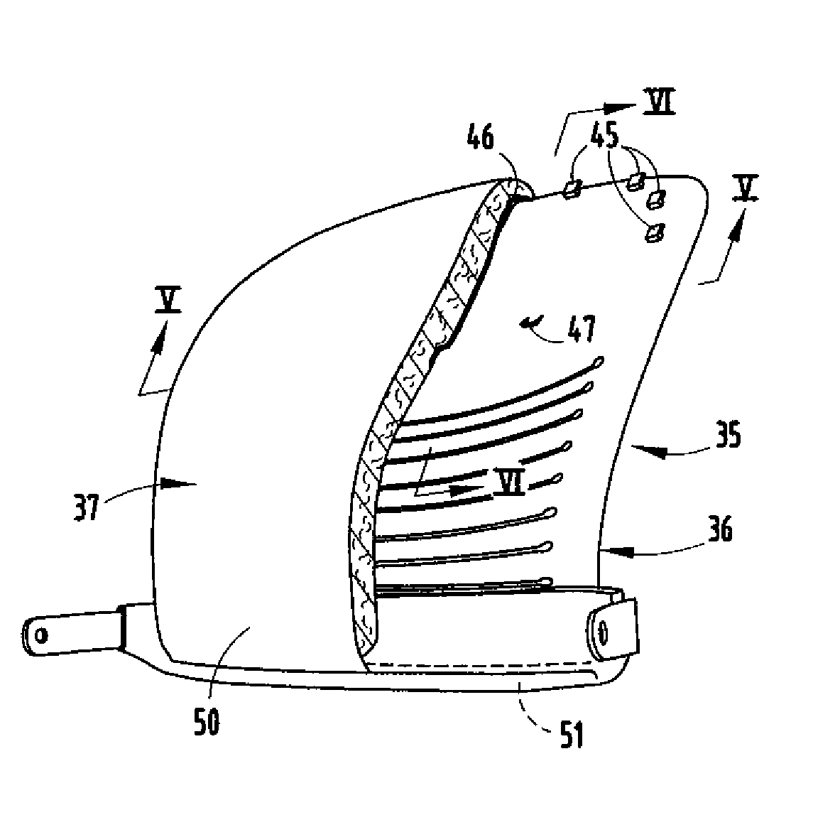
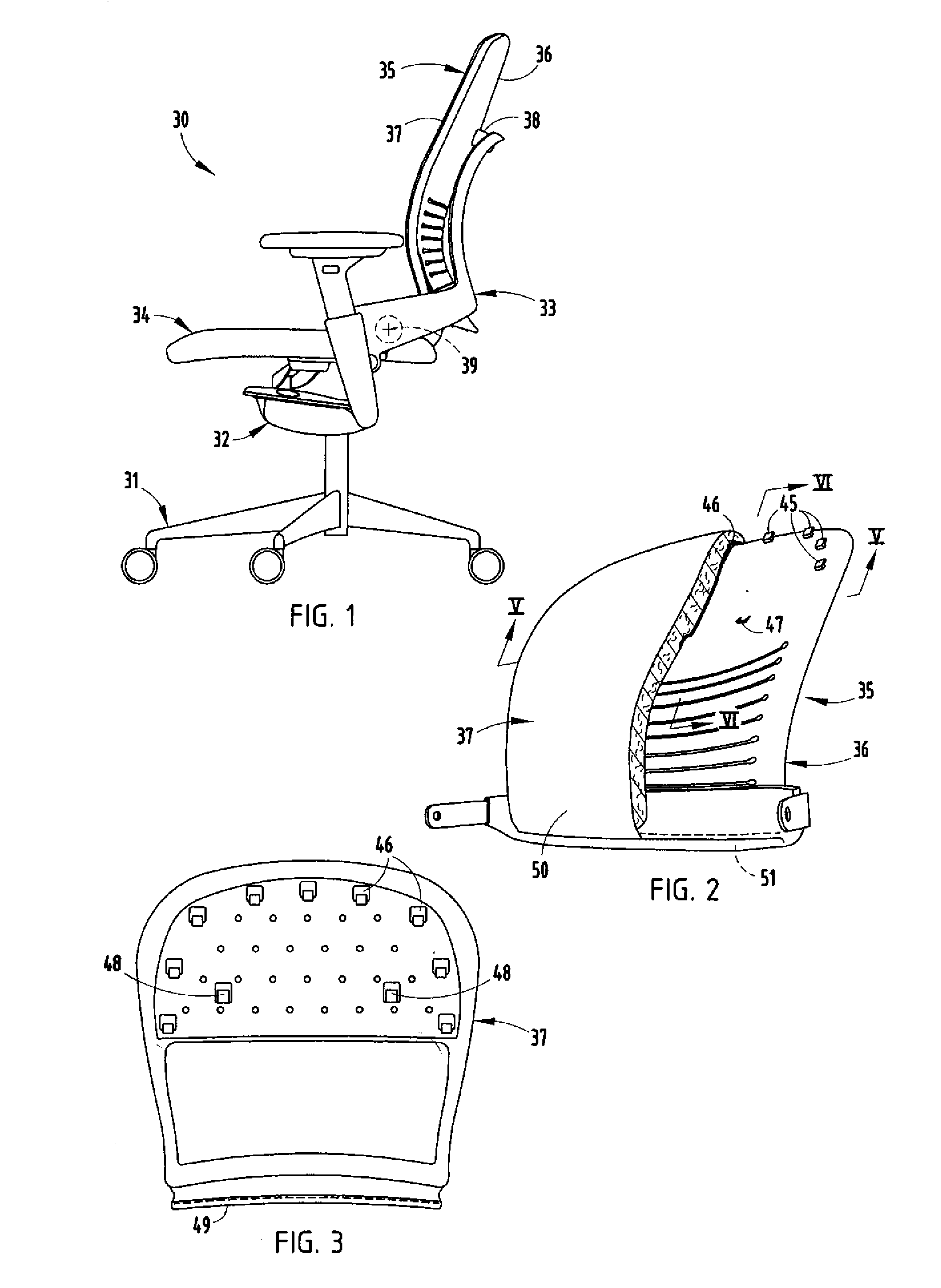
[0026]A seating unit 30 (FIG. 1) includes a base 31, an underseat control 32, a back frame 33 operably supported in the base 31, and a seat 34 operably supported at its front on the base 31 and at its rear on the back frame 33 for synchronous movement of the seat 34 upon recline of the back frame 33. A back assembly 35 is supported on the back frame 33, and includes a back support 36 (also sometimes called a back “shell” or “support panel”) and a cushion subassembly 37 on the back support 36. The back support 36 is operably supported on the back frame33 at top and bottom pivots 38 and 39 (FIGS. 1-2) and is flexible in its lumbar region and forwardly biased, such that it provides a seated user with exceptional comfort and ergonomic support, especially to the user's lower back. The reader is referred to Knoblock U.S. Pat. No. 5,975,634 and Peterson U.S. Pat. No. 6,425,637 if additional information is desired about the interaction and cooperation of these types of components in support...


PUM

PropertyMeasurementUnit
polymericaaaaaaaaaa
thicknessaaaaaaaaaa
thickaaaaaaaaaa

Abstract

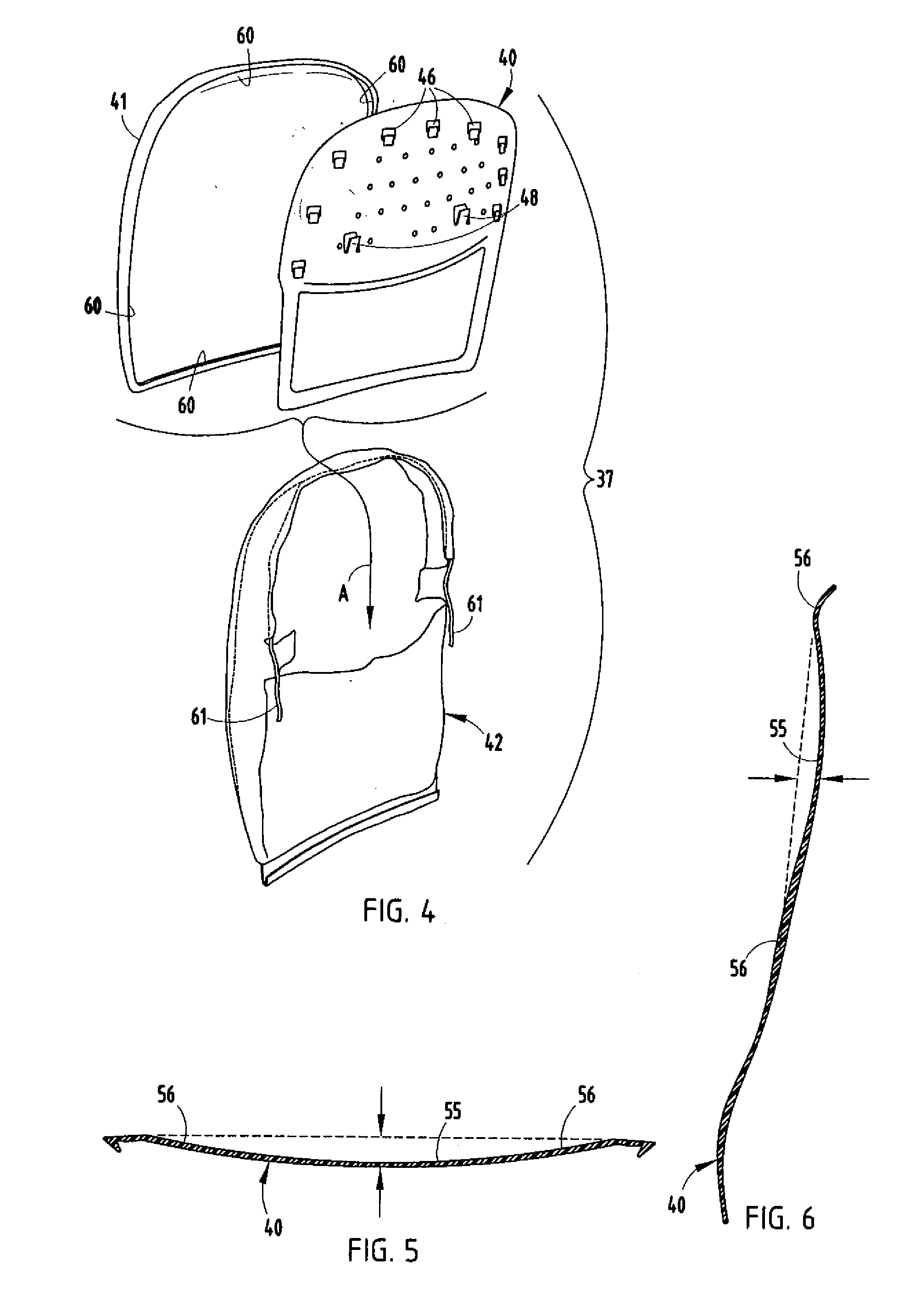
A cushion subassembly includes a support, a cushion of non-woven polymeric (PET) or PETE fibers with a formed edge that wraps over an edge of the support, and an upholstery sock pulled onto and covering the support and the cushion. The formed edge has sufficient mechanical structure to retain the cushion on the support as the upholstery sock is pulled onto the support. A back support shell supports the cushion assembly, and has first fasteners that engage in a first direction and second fasteners that prevent disengagement. The cushion assembly is stressed during assembly, especially at corners, but is thermally stress-relieved after assembly to relax the polymeric fibers and the upholstery sock to a state of minimized balanced tension. The back support shell includes a shallow depression on its face. The cushion fills the depression sufficient to eliminate loose fabric but provides a same force deflection curve across its shape.

Description

CROSS-REFERENCE TO RELATED APPLICATION[0001]This application is a divisional application of Ser. No. 11 / 296,679, filed Dec. 7, 2005, entitled SEATING UNIT WITH FORMED CUSHION, AND MANUFACTURING METHOD.BACKGROUND[0002]The present invention relates to seating units, and more particularly relates to a chair having a formed cushion, where the cushion is shaped to mate with a stiffener in a manner adapted to facilitate subassembly into an upholstery sock, and also shaped to optimize comfort and appearance in the final seating product. Further, the present invention concerns methods of assembly related to the above.[0003]Many chairs include a back structure covered by an upholstery subassembly, where the upholstery subassembly forms a sock-like hollow covering that can be pulled onto the back structure to aesthetically cover all or part of the back structure. For example, see U.S. Pat. No. 6,425,637 to Peterson. A common problem in many such chair designs is that the sock must be tight en...

Claims


Application Information

Patent Timeline
Patent Type & Authority Applications(United States)
IPC IPC(8): A47C7/02
CPCA47C7/185Y10T29/481B29C43/146B29C43/18B29C43/36B29C43/3607B29C63/04B29D99/0092B29K2105/06B29L2031/3041B68G7/10D04H1/005Y10T29/49863Y10T29/49865Y10T29/4987Y10T29/486A47C7/40
Inventor PETERSON, GORDON J.
Owner STEELCASE INC
Learn More