Snowmobile assembly

a technology for snowmobiles and components, applied in the direction of vehicle components, rider propulsion, transportation and packaging, etc., can solve the problems of limited travel for existing snowmobile suspension systems, significant limitations of snowmobile riders, and limited front suspension travel, so as to improve handling, optimize engine positioning, and increase the effect of energy absorption

Inactive Publication Date: 2011-09-13
LUCARELLI LANCE
View PDF10 Cites 4 Cited by
  • Summary
  • Abstract
  • Description
  • Claims
  • Application Information

AI Technical Summary

Benefits of technology

[0009]Embodiments of the present invention relate to an improved snowmobile assembly yielding increased energy absorption in its suspension, improved handling, optimized engine positioning and lower center of gravity. As described herein, embodiments of the present invention provide a redesigned drive system fixed rail (“DSFR”), alternatively called a drive system stationary rail (“DSSR”), and a brake system mounted on the fixed rail. Another aspect of certain embodiments of the present invention provides the driver and braking apparatus positioned on the fixed rail allowing for a quick change gear system (“QCS”) in an easily accessible gear box.
[0010]In accordance with embodiments of the present invention, by moving the driver out of tunnel there is a shorter distance for the rubber drive track yielding less weight and minimized tensioning issues. In addition, shock absorbers may not mounted inside of fixed rail as with a traditional suspension system, allowing enhanced suspension displacement in a compressed state. Furthermore, shorter dimension of the snowmobile and this yields a lighter snowmobile.
[0011]With many embodiments of the present invention, by having increased suspension with the front swing arm, there is increased suspension with the rear swing arms, which in turn provides an increased suspension with a front ski suspension system. Additional benefits of embodiments of the present invention provide a unique and optimized engine positioning, gas tank positioning, and ski placement. Furthermore, because of the features of embodiments of the present invention, the overall snowmobile length is shortened, and the steering and handling of the snowmobile is greatly enhanced.

Problems solved by technology

In many known systems, the front suspension arm is limited to minimal suspension travel because of a plastic driver fixed in the snowmobiles tunnel, over which the rubber drive track must travel.
Thus, the amount of travel for existing snowmobile suspension systems are limited to about 2 to 6 inches for the front suspension arms of true vertical displacement and about 6 to 9 inches for the rear suspension arms of true vertical displacement.
However, while these designs may be sufficient for certain conditions, there are significant limitations which snowmobile riders encounter on a frequent basis, for example, when travelling over moguls or on bumpy terrain.

Method used


Image

  • Snowmobile assembly
  • Snowmobile assembly
  • Snowmobile assembly

Examples


Embodiment Construction

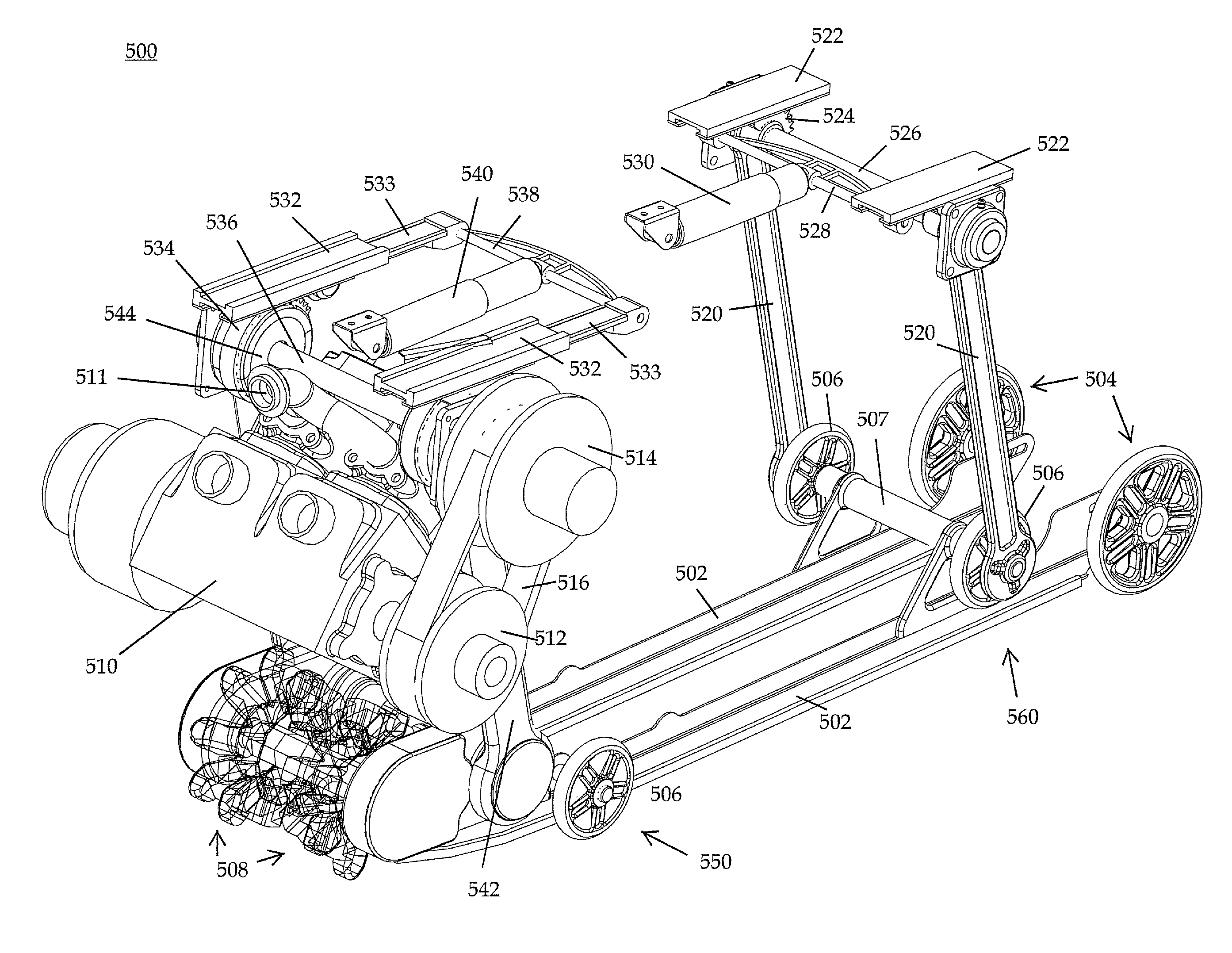
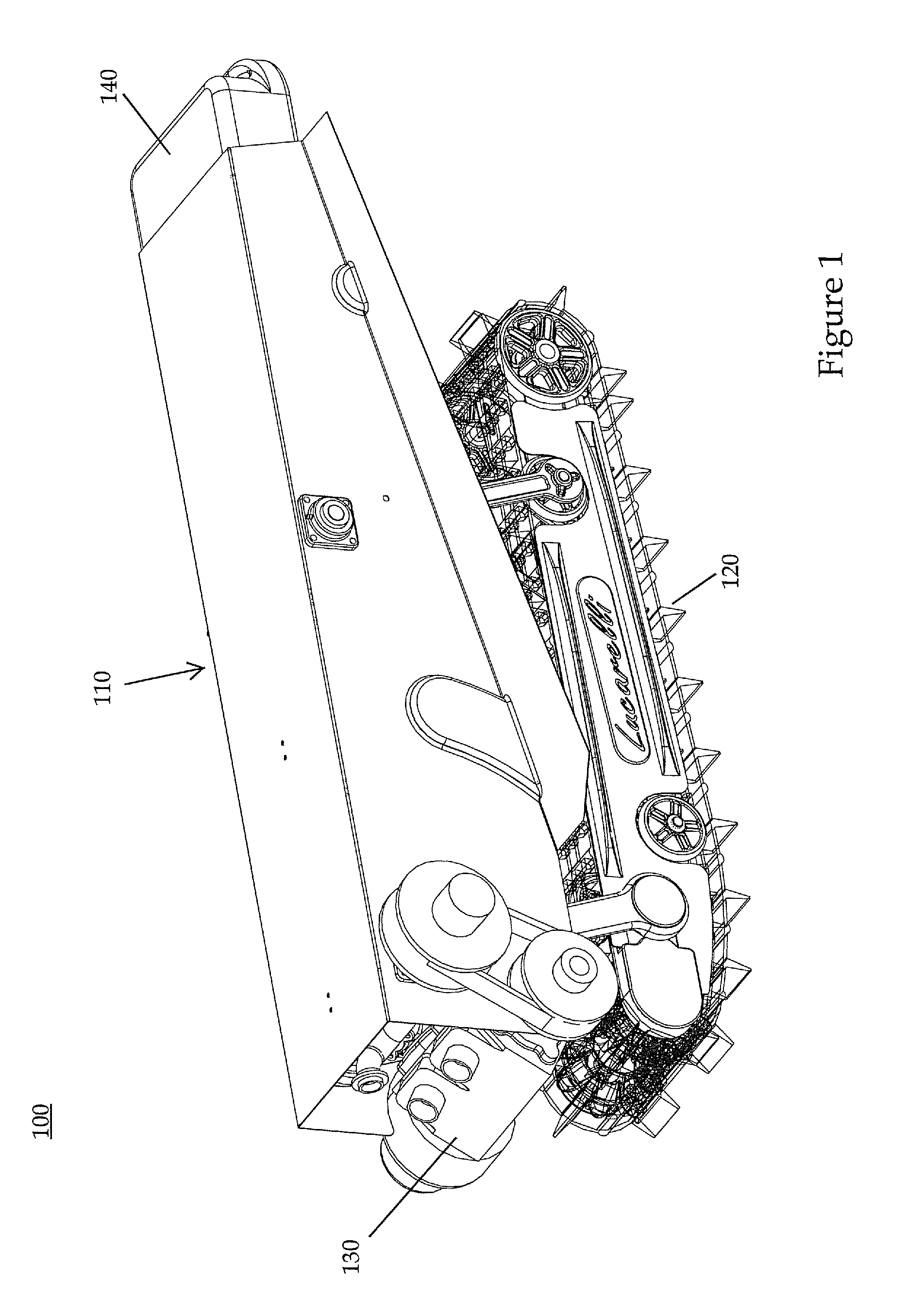
[0030]Embodiments of the present invention relate to an improved snowmobile assembly yielding increased energy absorption in its suspension, improved handling, optimized engine positioning and lower center of gravity. FIG. 1 depicts a perspective view of a rear portion of a snowmobile assembly in accordance with one embodiment of the present invention. Generally, the visual middle and rear portion of a snowmobile assembly 100 comprises at least a tunnel 110, a track 120, an engine 130 (and components therewith), and an optional bumper 140. The tunnel 110, or body of the snowmobile, is generally a fiberglass, aluminum or metallic shell, surrounding the internal components of the snowmobile (not shown), which are described in greater detail below. In certain embodiments, the tunnel 110 may comprise a plurality of panels, affixed to various components of the snowmobile, such that certain other components of the snowmobile may extend through the tunnel 110 during operation. The tunnel 1...


PUM


Abstract

Embodiments of the present invention relate to an improved snowmobile assembly yielding increased energy absorption in its suspension, improved handling, optimized engine positioning and lower center of gravity. In one embodiment, a rear snowmobile suspension comprises a frame comprising a pair of opposing, longitudinally extending, transversely spaced fixed rails, a pair of rear swing arms pivotably connected on respective first ends to a rear portion of the frame, one on each of a first and a second fixed rail, a front swing arm pivotably connected on a first end to a front portion of the frame on the first fixed rail, and a front drive arm pivotably connected on a first end to a front portion of the frame on the second fixed rail, opposing the front swing arm, wherein the front drive arm houses a portion of the drive assembly for driving the snowmobile.

Description

BACKGROUND OF THE INVENTION[0001]1. Field of the Invention[0002]Embodiments of the present invention generally relate to a snowmobile assembly. More specifically, embodiments of the present invention relate to an improved snowmobile assembly yielding increased energy absorption in its suspension, improved handling, optimized engine positioning and lower center of gravity.[0003]2. Description of the Related Art[0004]Performance characteristics of snowmobiles, including the comfort of the ride, depend upon a variety of systems and components, including the snowmobile suspension design, and the length and weight of the snowmobile. Typically, a snowmobile suspension includes two systems, a front suspension system for the skis and a rear suspension system for the track.[0005]The rear suspension of a snowmobile supports an endless track driven by the snowmobile engine to propel the machine. The track is supported beneath the vehicle chassis by a suspension that is designed to provide a co...

Claims


Application Information

Patent Timeline
Patent Type & Authority Patents(United States)
IPC IPC(8): B62M27/02
CPCB62M27/02B62M2027/026
Inventor LUCARELLI, LANCE
Owner LUCARELLI LANCE
Why Eureka
Try Eureka