Lamp with double filament

Inactive Publication Date: 2009-01-15
KONINKLIJKE PHILIPS ELECTRONICS NV
View PDF3 Cites 2 Cited by
  • Summary
  • Abstract
  • Description
  • Claims
  • Application Information

AI Technical Summary

Benefits of technology

[0004]It is an object of the invention to provide a lamp which has an improved lifetime and which is easy to manufacture.
[0006]According to the invention, a filament is added around the incandescent body, which filament is in contact or close to the walls of the lamp vessel. As a consequence, when the incandescent body is heated at a relatively high temperature and sagging occurs, this sagging is absorbed by the filament, which has a plurality of contact points with the lamp vessel. As the filament is arranged around a substantial part of the incandescent body, the sagging is reduced compared with the lamps of the prior art, where supports are provided only locally around the incandescent body. Moreover, the manufacturing process of a lamp in accordance with the invention is simplified, because only one step is required, which step consists in arranging the filament around the incandescent body.
[0009]Preferably, the lamp vessel is made from quartz. The lamp in accordance with the invention can then be used at high temperature, because the quartz resist to relatively high temperatures. This reduces the risk of burst of the lamp, even if the filament is in contact with the lamp vessel.

Problems solved by technology

However, the applicant has noticed that, in a tubular lamp such as described in US 2003 / 0001475, sagging of the incandescent body still occurs, especially when the tubular lamp has been used for a relatively long time.
Moreover, manufacturing such a lamp requires a long and complicated process, as it requires many steps for adding the supports one by one around the incandescent body.

Method used


Image

  • Lamp with double filament
  • Lamp with double filament
  • Lamp with double filament

Examples


Embodiment Construction

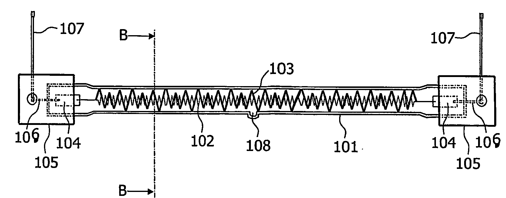
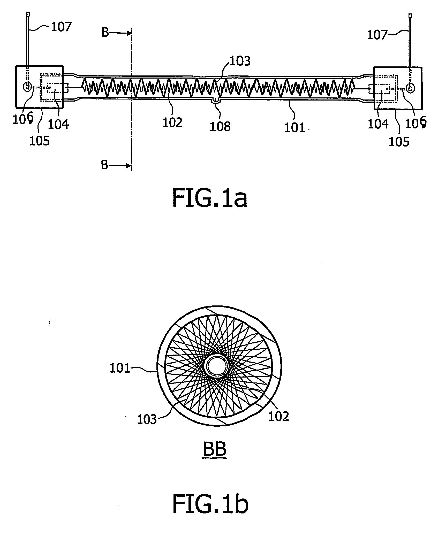
[0015]A lamp in accordance with a first embodiment of the invention is depicted in FIGS. 1a and 1b. FIG. 1b is an enlarged cross-section in the plane BB of FIG. 1a. For reasons of convenience, the respective dimensions of the elements of the lamp may not correspond on FIG. 1a and FIG. 1b. This lamp comprises a lamp vessel 101, an incandescent body 102, a filament 103 and current supply conductors 106. The lamp further comprises caps 105, foils 104, current wires 107 and an exhausting pipe 108. Although a double-ended lamp has been represented in FIG. 1a, the invention may be applied to a single-ended lamp.

[0016]The incandescent body 102, which is for example a tungsten wire, has its extremities connected to the foils 104, which are for example pieces of molybdenum to which the extremities of the incandescent body 102 are welded. Current supply conductors 106 are also welded to the foils 104. The current supply conductors 106 are connected to the current wires 107. This can be done b...


PUM


Abstract

The present invention relates to a lamp comprising a lamp vessel (101) having an inner diameter and an incandescent body (102) arranged in the lamp vessel and connected to current supply conductors (106). The lamp further comprises a filament (103) arranged around said incandescent body along at least half the length of said incandescent body, which filament has an outer diameter substantially equal to the inner diameter of the lamp vessel.

Description

FIELD OF THE INVENTION[0001]The present invention relates to a tubular lamp.[0002]The invention finds its application, for example, in a heating system designed for industrial purposes such as curing of synthetic resins by heat, drying of paper, baking of paints or semiconductors manufacturing.BACKGROUND OF THE INVENTION[0003]Patent US 2003 / 0001475 published Jan. 2, 2003 describes a tubular lamp comprising a lamp vessel with an incandescent body arranged in the lamp vessel and connected to current supply conductors. In order to locate axially the incandescent body within the lamp vessel, the tubular lamp comprises supports added around the incandescent body periodically along the incandescent body length. These supports reduce the sagging of the incandescent body that occurs when the incandescent body is heated at a relatively high temperature. Reducing the sagging of the incandescent body is important, because the sagging reduces the lifetime of the tubular lamp. However, the appli...

Claims


Application Information

Patent Timeline
IPC IPC(8): H01J1/94H01KH01K1/18H05B3/00
CPCH01K1/18H05B2203/032H05B3/0066H05B3/0047
Inventor GUEUSQUIN, ERIC
Owner KONINKLIJKE PHILIPS ELECTRONICS NV
Why Eureka
Try Eureka