

Liquid crystal display apparatus
a liquid crystal display and display device technology, applied in the direction of instruments, static indicating devices, etc., can solve the problems of increased space for mounting circuit substrates connected to liquid crystal panels, increased cost, and reduced memory capacity, and video is displayed brilliantly
- Summary
- Abstract
- Description
- Claims
- Application Information
AI Technical Summary
Benefits of technology
Problems solved by technology
Method used
Image

Examples
first embodiment
[0067]Referring now to FIG. 1 to FIG. 4, an OCB-type liquid crystal display apparatus according to the invention will be described.
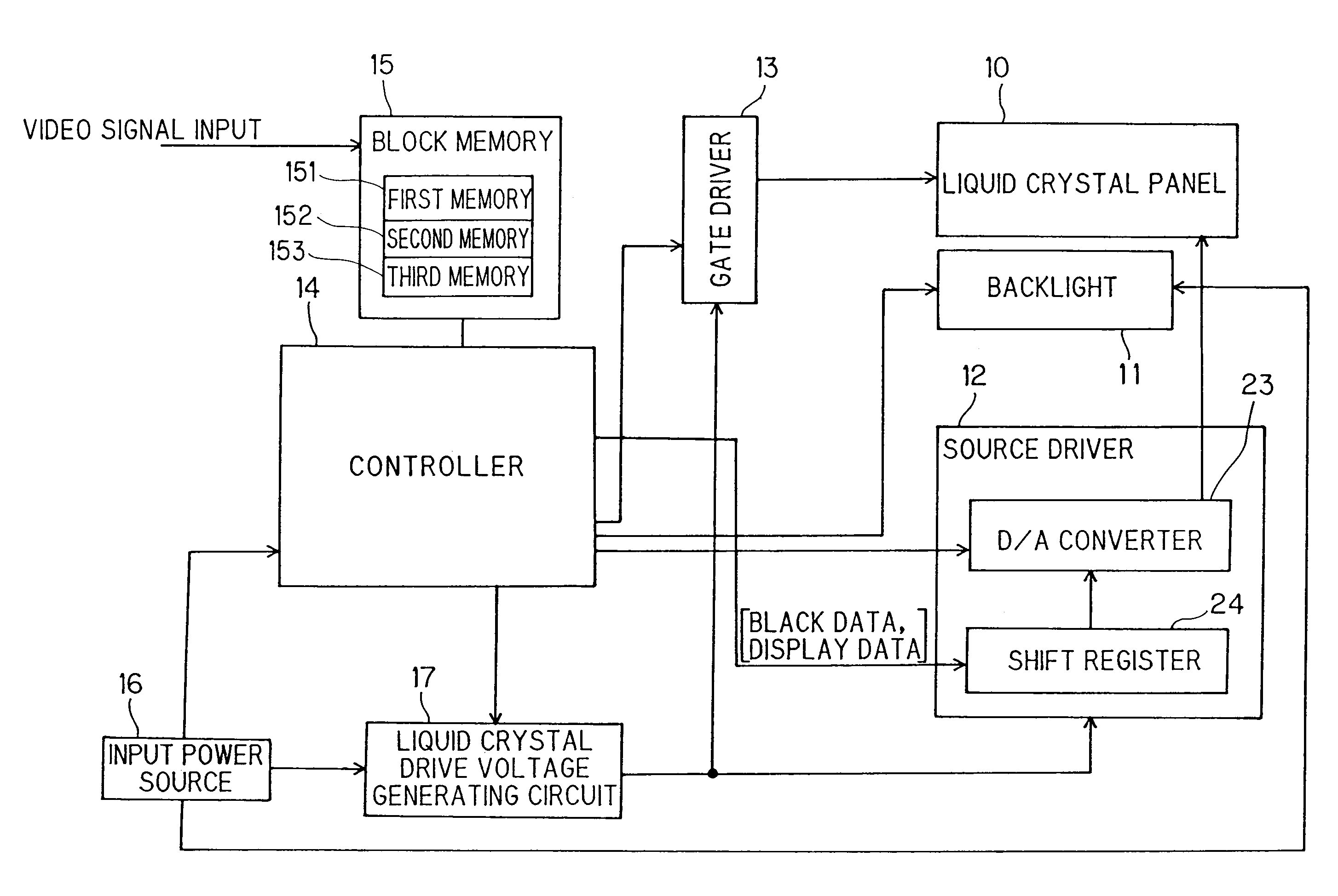
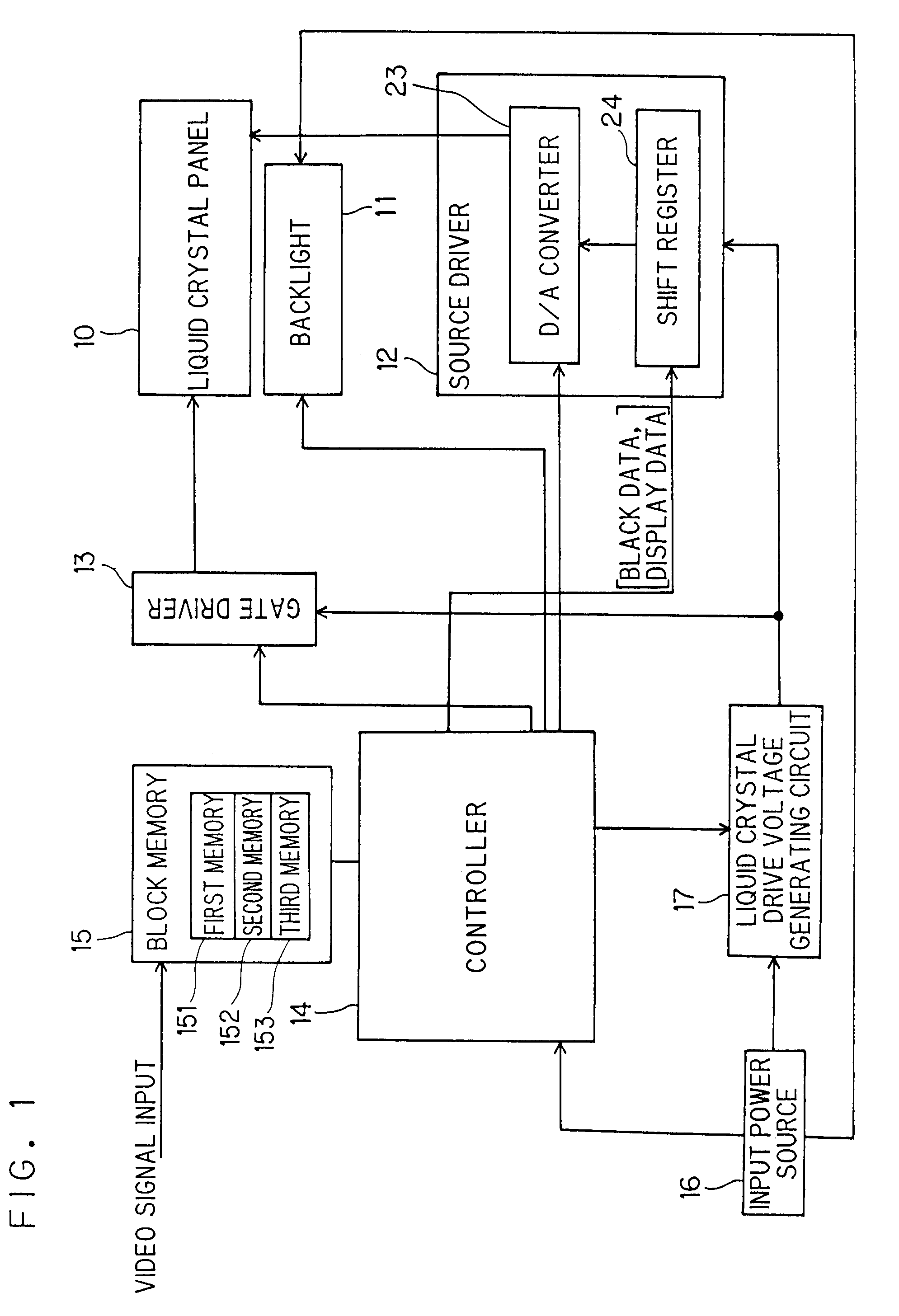
[0068]Referring now to FIG. 1, a configuration of the liquid crystal display apparatus according to the first embodiment will be described. FIG. 1 is a block diagram showing the configuration of the OCB-type liquid crystal display apparatus.
[0069]The OCB-type liquid crystal display apparatus includes, for example, a liquid crystal panel 10 of a size from 7 to 9 inches, a backlight 11, a source driver 12, a gate driver 13, a controller 14, a block memory 15, an input power source 16 and a liquid crystal drive voltage generating circuit 17.
[0070]The liquid crystal panel 10 includes an array substrate and an opposed substrate, and the array substrate includes signal lines and scanning lines arranged so as to be orthogonal to each other and TFTs (thin film transistors) at intersections thereof, and liquid crystal of OCB mode is interposed between the array s...
third embodiment
[0148]Referring now to FIG. 7 and FIG. 8, the liquid crystal display apparatus will be described.
[0149]In the liquid crystal display apparatus in the first embodiment, the luminance of the LEDs 112 and the gamma value were determined for each block. In the method of controlling the luminance of the backlight 11 as described above, when the difference in luminance between adjacent blocks is increased, there may be a case in which lines are visualized at boundaries between the adjacent blocks.
[0150]Therefore, in the liquid crystal display apparatus in the third embodiment, the method of controlling the luminance of the backlight 11 so as to avoid generation of lines at the boundaries between the adjacent blocks is provided.
[0151]Referring to FIG. 7, the method of controlling the luminance in the third embodiment will be described while comparing with the method of controlling in the first embodiment.
[0152]A part (a) in FIG. 7 shows a state on input of the video signals in one frame p...
fourth embodiment
[0170]Referring now to FIG. 9, a fourth embodiment will be described.
[0171]In the third embodiment, in order to prevent the lines at the boundaries between adjacent blocks from being visualized, the luminance is determined with respect to the luminance of the block immediately before. However, in the fourth embodiment, the luminance is determined with respect to an average value of the luminance values in the respective blocks in the frame immediately before the current frame.
[0172]A part (a) in FIG. 9 represents the input of the video signals and the line position in each frame.
[0173]A part (b) in FIG. 9 represents the state of luminance for each frame described in the first embodiment. In this state, as described in the second embodiment, there is a case in which lines may be generated between adjacent blocks.
[0174]As shown in FIG. 9(c), an average value of the luminance of the respective blocks in the frame immediately before the current frame calculated by the backlight luminanc...
PUM
 Abstract
Description
Claims
Application Information