
Line Printer

a printer and line technology, applied in the field of line printers, can solve the problems of degradation of printing quality and printing quality, and achieve the effect of suppressing degradation of printing quality

Active Publication Date: 2009-01-15
SEIKO EPSON CORP
View PDF3 Cites 6 Cited by
  • Summary
  • Abstract
  • Description
  • Claims
  • Application Information

AI Technical Summary

Benefits of technology

[0008]Given the problem described above, the problem to be solved by the present invention is that of performing printing using a dithering mask capable of suppressing degradation of printing quality even when there is positional shift between the print heads in a printer that is provided with a plurality of print heads disposed in a line across the range of printing. An additional object of the present invention is to characterize a preferred dithering mask used in this type of line printer.
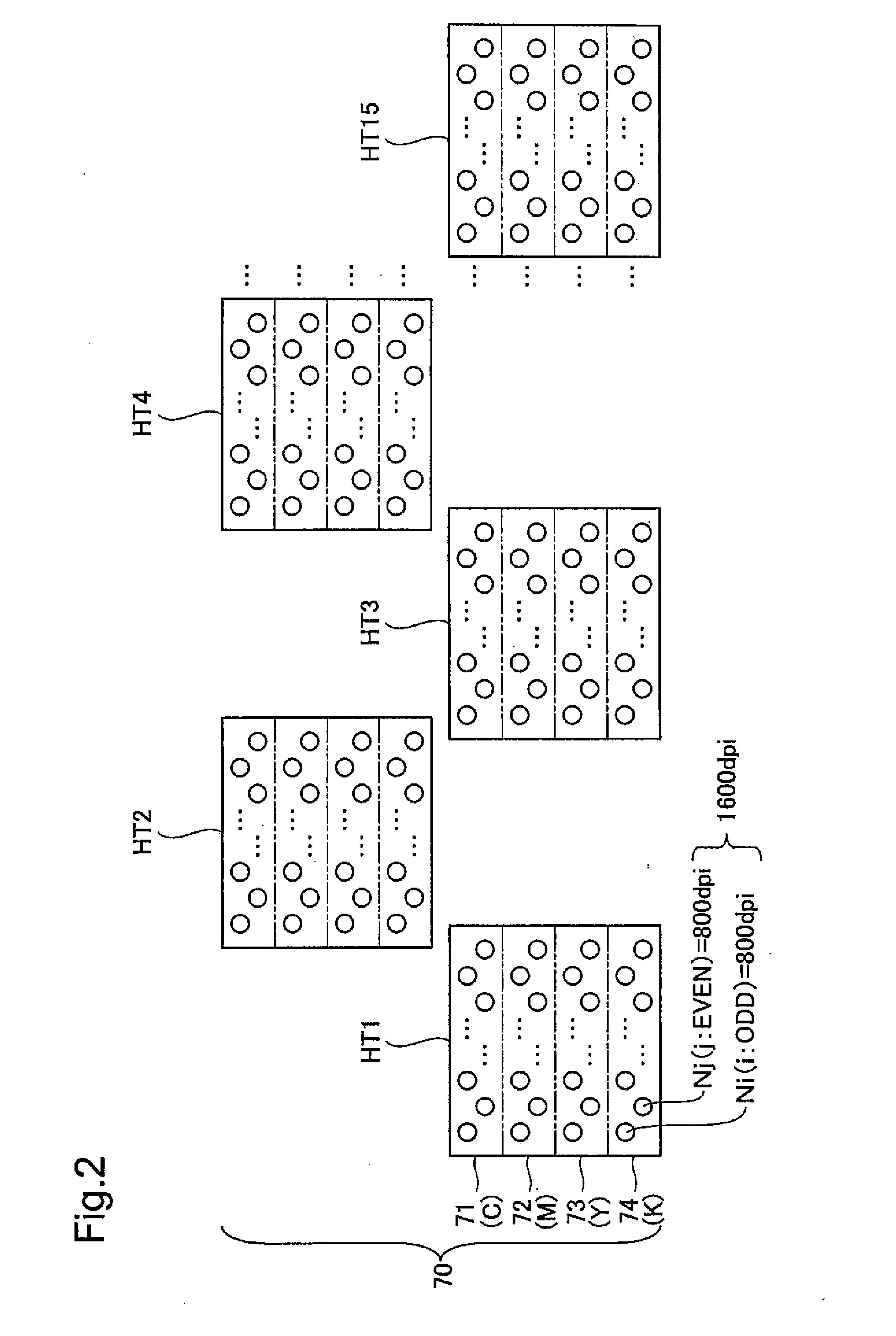
[0018]In a line printer of this structure, the dithering mask is produced through combining sets of threshold values that structure portions of base dithering masks, taking into consideration the dispersion characteristics of dots in each postulated positional shift pattern. Consequently, even if there are positional shifts between the plurality of print heads, it is possible to suppress degradation of the printing quality through ensuring the dispersion characteristics of the print dots by performing the half toning process using a dithering mask that is assembled corresponding to the positional shifts.
[0025]In a line printer structured in this way, the dithering mask is formed using a portion of a base dithering mask, which takes into account the dot dispersion characteristics, as a set of shared threshold values relative to a positional shift pattern that exhibits a non-shifted state between the plurality of print heads, and if the half toning process is performed so as to apply the set of shared threshold values to the pixels that are not affected by positional shift between the printer heads, then it is possible to maintain excellent dot dispersion characteristics even in a printing region corresponding to the set of shared threshold values.

Problems solved by technology

Given this, a shift of the placement position of the print head from the proper position, even if minute, will cause a degradation in the printing quality.
Securing this type of extremely high precision positioning, is extremely difficult in practice, and thus a degradation of printing quality due to positional shift of the print head is a problem inherent to this type of line printer.

Method used


Image

  • Line Printer
  • Line Printer
  • Line Printer

Examples


embodiment

A. Embodiment

[0049]A-1. Schematic Structure of the Printer

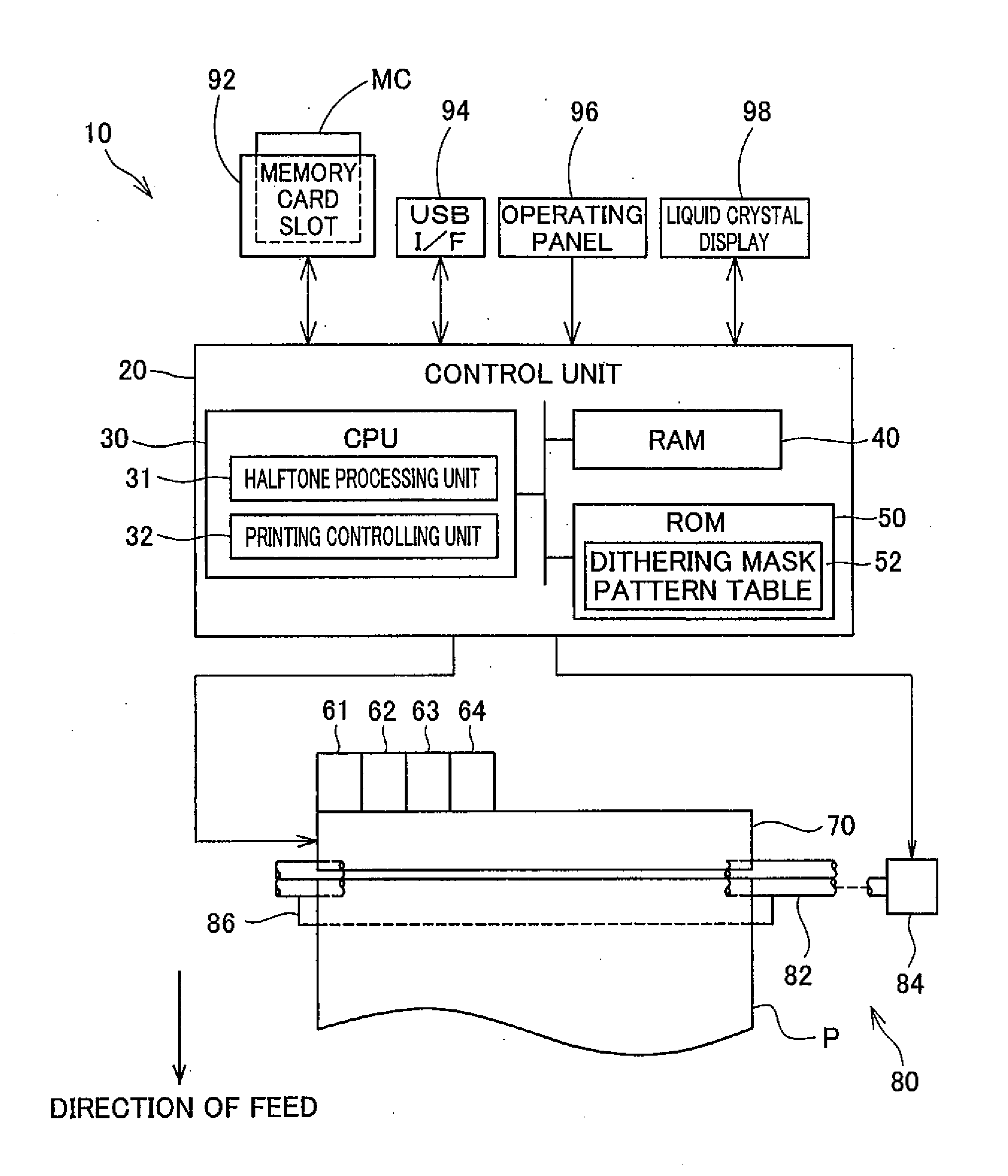
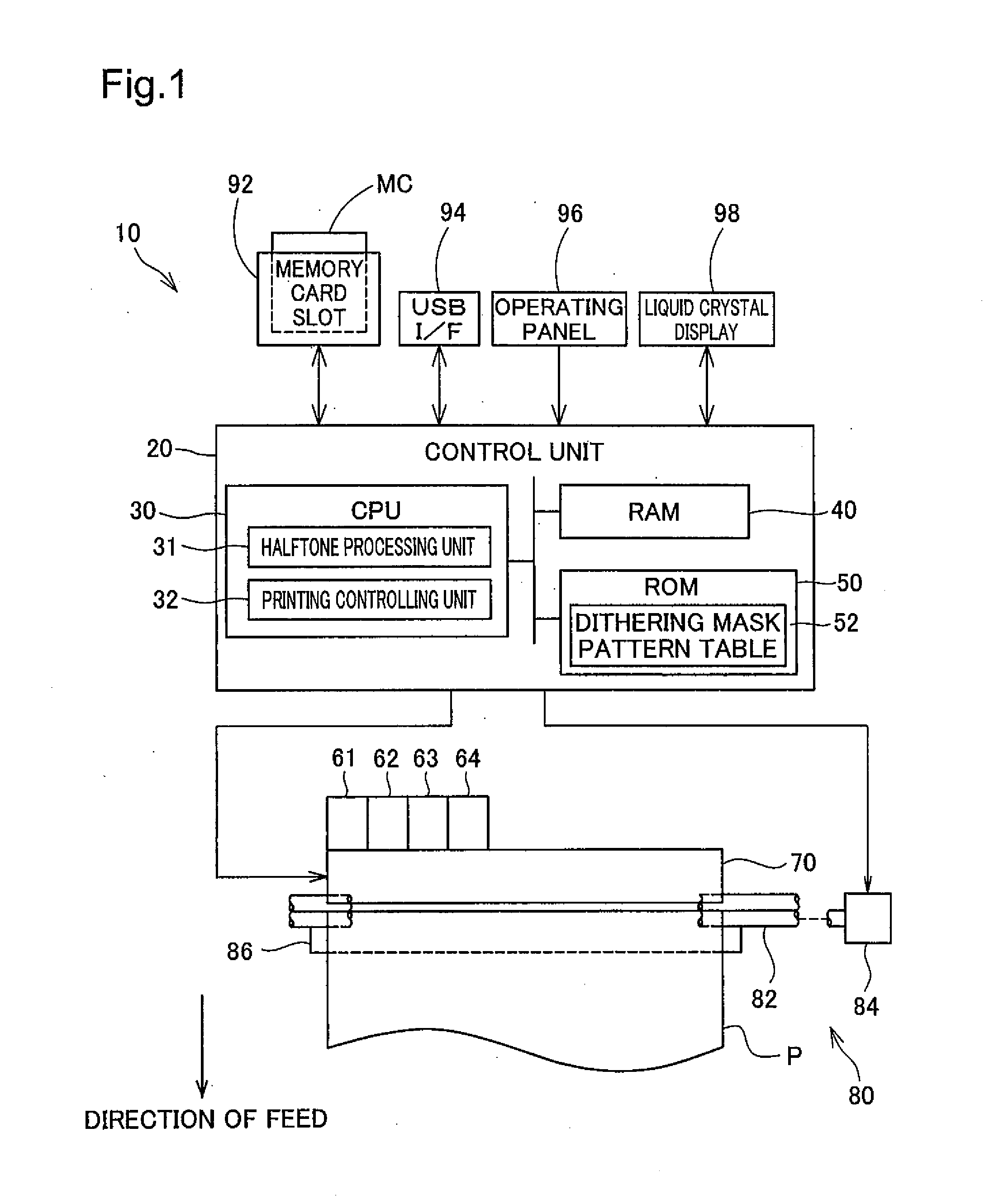
[0050]FIG. 1 is an explanatory diagram illustrating a schematic structure of a printer 10 as an embodiment of the present application. The printer 10 is an inkjet-type line printer, and, as shown in the figure, comprises a control unit 20, ink cartridges 61 through 64, a printer head 70, a paper feeding mechanism 80, and the like. The ink cartridges 61 through 64 correspond to the respective inks that produce the colors of cyan (C), magenta (M), yellow (Y), and black (K). Of course, the types and numbers of inks are not limited thereto.

[0051]The printer head 70 is a line head-type printer head, and is provided with a plurality of thermal-type nozzles disposed in essentially a line on the bottom surface thereof. Each of the inks in the ink cartridges 61 through 64 is provided to a nozzle that is positioned on the bottom surface of the printer head 70 through an introduction tube, not shown, and ink is sprayed from these nozzle...


PUM


Abstract

A plurality of types of positional shift postulated patterns are postulated wherein the positional shift of print head tips in a printer are postulated to have positional shift directions and distances. For each of the postulated positional shift postulated patterns, a base dithering mask is generated considering the ability to produce excellent dot dispersion characteristics when this postulated positional shift has occurred. Additionally, optimal dithering masks are generated through multiply combining the sets of threshold values that comprise the base dithering masks. Doing so enables the suppression of degradation of printed image quality, even when there are positional shifts between the print heads, in a half toning process for printing using a printer that is provided with a plurality of print heads that are arranged in a line across a printing range.

Description

CLAIM OF PRIORITY[0001]The present application claims priority from Japanese application P2007-182323A filed on Jul. 11, 2007, the content of which is hereby incorporated by reference into this application.BACKGROUND[0002]1. Field of the Invention[0003]The present invention relates to a line printer that is provided with a plurality of printing heads, disposed across a printing range.[0004]2. Description of the Related Art[0005]In inkjet-type line printers, ink droplets are sprayed from nozzles of print heads that are disposed in essentially a single line in a direction that is perpendicular to the direction of feeding of printer paper as the printer paper is being fed, to adhere to the printer to print text and graphics.[0006]In line printers, in a thermal printer, for example, typically a printer head is formed with a plurality of print heads disposed in a line. The use of a plurality of print heads in this way is to improve the yields of the printer heads that are manufactured by...

Claims


Application Information

Patent Timeline
IPC IPC(8): H04N1/04
CPCH04N1/4051
Inventor KAKUTANI, TOSHIAKI
Owner SEIKO EPSON CORP
Learn More