Inertial drive actuator

a technology of inertial drive and actuator, which is applied in the direction of piezoelectric/electrostrictive/magnetostrictive devices, mountings, instruments, etc., can solve the problems of deteriorating the detection accuracy of position detection using capacitance and deteriorating assembly efficiency, and achieves high position detection accuracy and easy assembly

Active Publication Date: 2009-01-15
OLYMPUS CORP
View PDF6 Cites 23 Cited by
  • Summary
  • Abstract
  • Description
  • Claims
  • Application Information

AI Technical Summary

Benefits of technology

[0009]The present invention has been made in view of the above described situation and has as an object to provide an inertial drive actuator that is easy to assemble and has high position detection accuracy.

Problems solved by technology

This is because variations in the gap (i.e. spatial variations and changes with time) between the electrodes that constitute a capacitor can deteriorate the detection accuracy in the position detection utilizing capacitance.
Thus, such requirements have been factors that deteriorate efficiency in assembling.

Method used


Image

  • Inertial drive actuator
  • Inertial drive actuator
  • Inertial drive actuator

Examples


first embodiment

[0040]In the following, the embodiments of the present invention will be described with reference to the drawings.

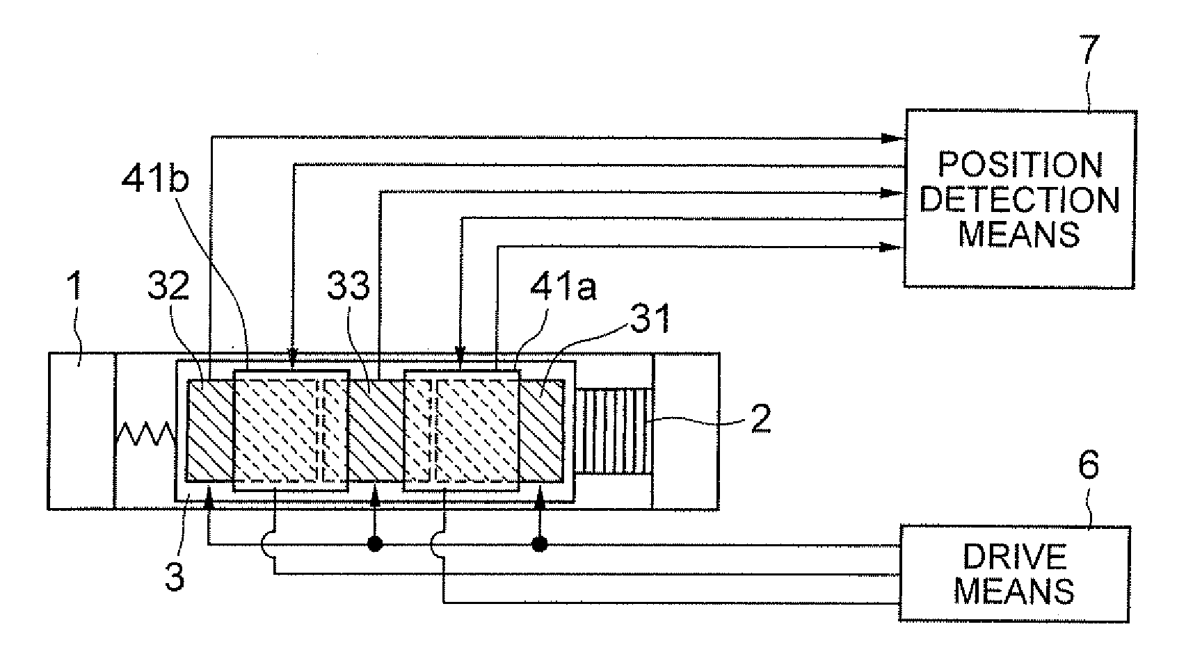
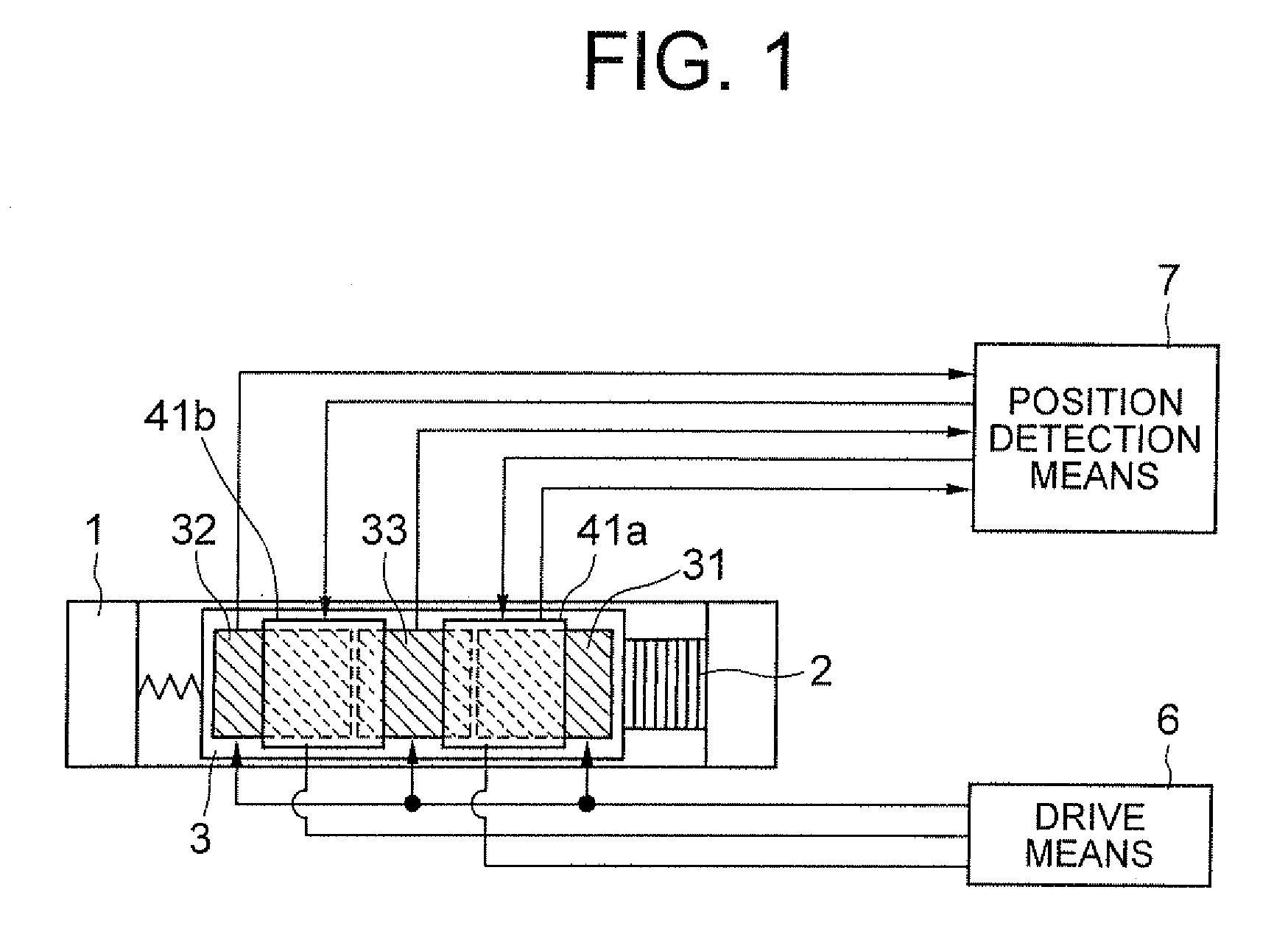
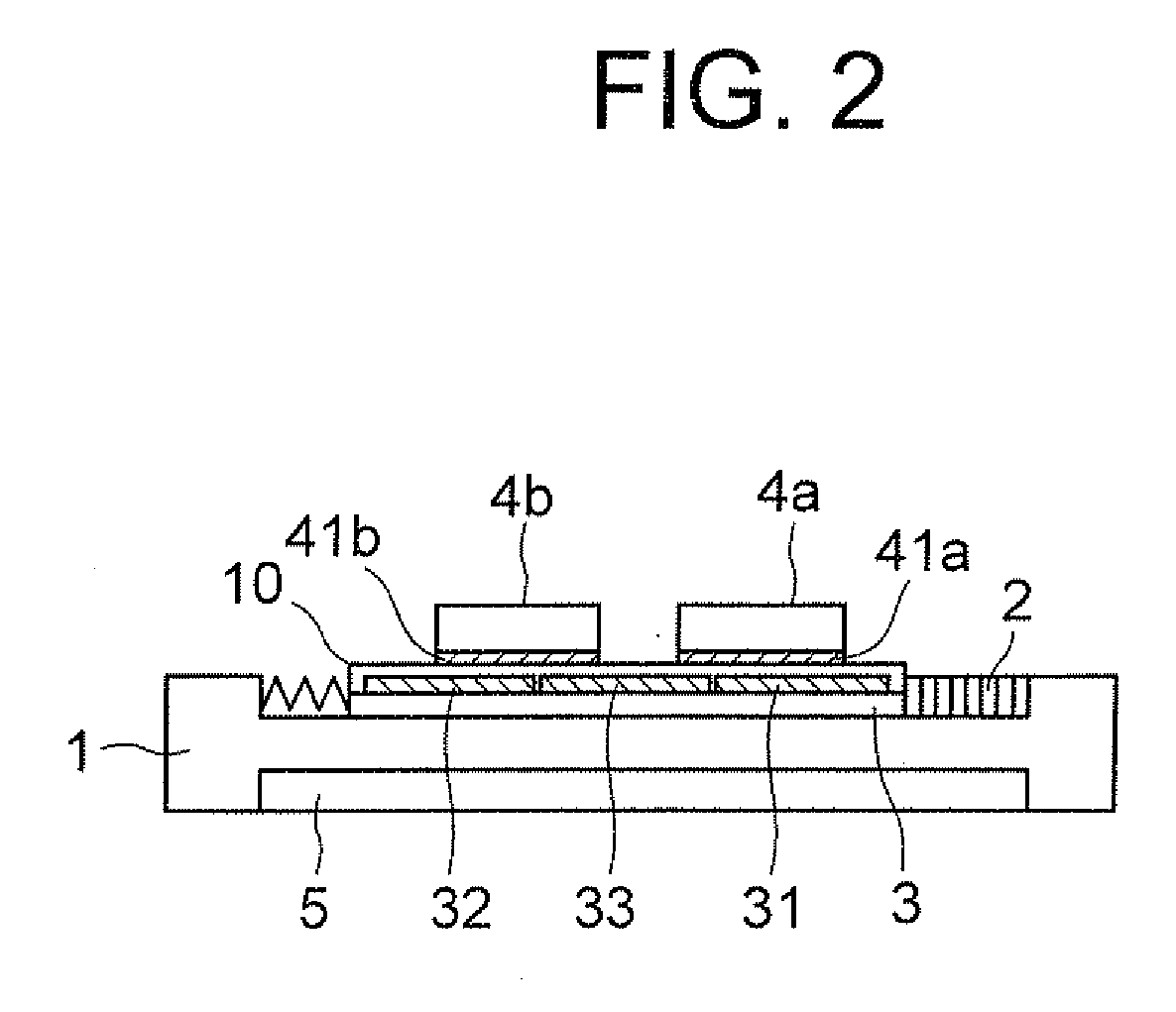
[0041]FIGS. 1 and 2 illustrate the configuration of the first embodiment. FIG. 1 is a plan view of an inertial drive actuator according to a first embodiment of the present invention, and FIG. 2 is a side view of the inertial drive actuator according to the first embodiment. The inertial drive actuator has a piezoelectric element 2, one end of which is fixed to a fixed member 1 and the other end of which is fixed to one end of a vibration substrate 3. On the vibration substrate 3 are moving bodies 4a and 4b that can move in the direction of vibration of the piezoelectric element 2. The moving bodies 4a and 4b are juxtaposed along the direction of movement thereof. First electrodes 41a and 41b are provided on the bottom surfaces of the moving bodies 4a and 4b respectively. Second electrodes 31, 32 and 33 are provided on the flat surface of the vibration substrate 3 that i...


PUM


Abstract

To provide an inertial drive actuator that is easy to assemble and achieves high accuracy in position detection, the actuator has a fixed member, a vibration substrate, a piezoelectric element (movement unit), first and second moving bodies that moves relative to the vibration substrate by inertia, a first electrode provided on the surface of each of the first and second moving bodies, a second electrode provided on a surface of the vibration substrate, an insulating film provided between the first electrode and the second electrode, a drive unit, and a position detection unit that detects the position of the moving body with respect to the vibration substrate based on capacitance of the portion in which the first electrode and the second electrode are opposed to each other.

Description

CROSS-REFERENCE TO RELATED APPLICATION[0001]The present application is based upon and claims the benefit of priority from the prior Japanese Patent Application No. 2007-180806 filed on Jul. 10, 2007; the entire contents of which are incorporated herein by reference.BACKGROUND OF THE INVENTION[0002]1. Field of the Invention[0003]The present invention relates to an inertial drive actuator.[0004]2. Description of the Related Art[0005]When a drive pulse with a waveform having a moderate rise and a subsequent steep fall is applied to a piezoelectric element, which is a kind of electro-mechanical transducer, the piezoelectric element expands slowly at the moderate rise of the drive pulse and contracts quickly at the steep fall of the drive pulse. There is a known inertial drive actuator that utilizes such characteristics. In the inertial drive actuator, drive pulses having the above described waveform are applied to a piezoelectric element to generate vibration having different speeds in ...

Claims


Application Information

Patent Timeline
Patent Type & Authority Applications(United States)
IPC IPC(8): G02B7/04
CPCG02B26/0858H02N2/025
Inventor MATSUKI, KAORU
Owner OLYMPUS CORP
Why Eureka
Try Eureka