Draw in-out apparatus for air circuit breaker

a draw-in-out apparatus and air circuit breaker technology, which is applied in the direction of contact mechanisms, switchgear with a retractable carriage, protective switch details, etc., can solve the problem that the draw-in-out apparatus having this structure cannot be applied to an air circuit breaker having large capacity and size, and the main body load is also increased, so as to achieve the effect of large capacity and siz

Inactive Publication Date: 2009-01-15
LS IND SYETEMS CO LTD
View PDF11 Cites 18 Cited by
  • Summary
  • Abstract
  • Description
  • Claims
  • Application Information

AI Technical Summary

Benefits of technology

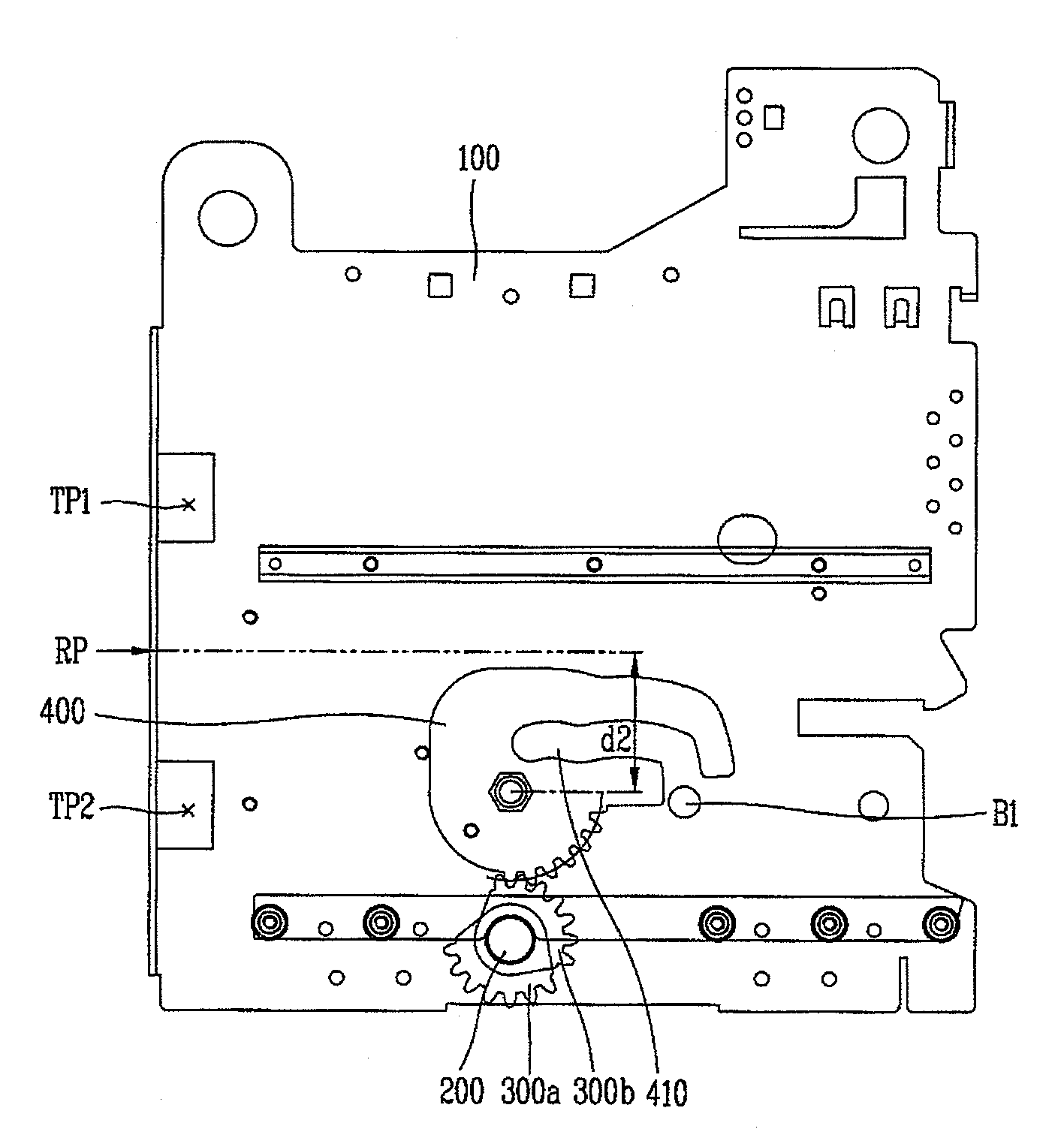
[0025]Therefore, the present invention is directed to providing a draw in-out apparatus for an air circuit breaker which is capable of effectively enduring a load of the main body and a reaction force generated when moving to a connected position and of being applied to an air circuit breaker having large capacity and size.

Problems solved by technology

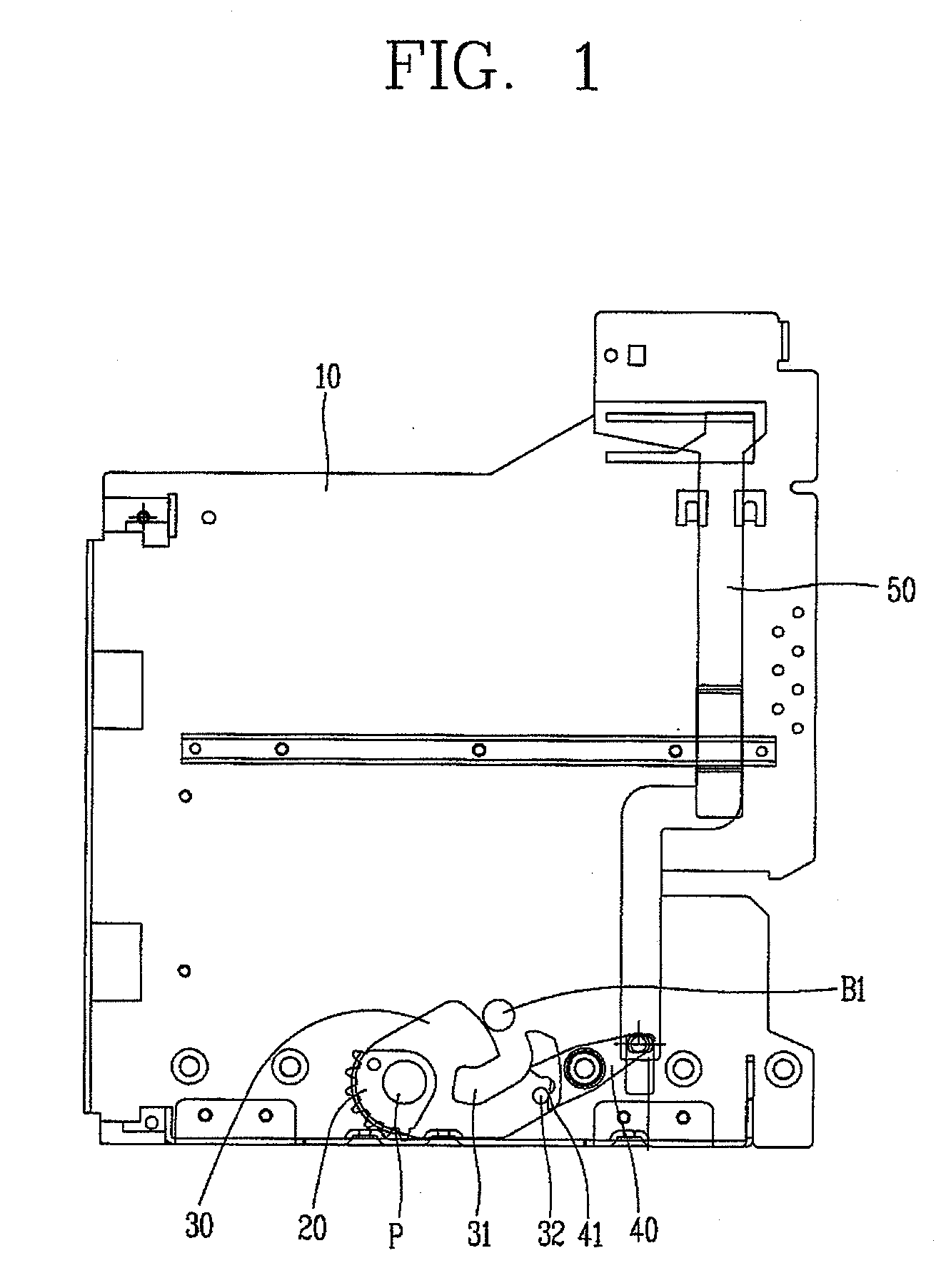
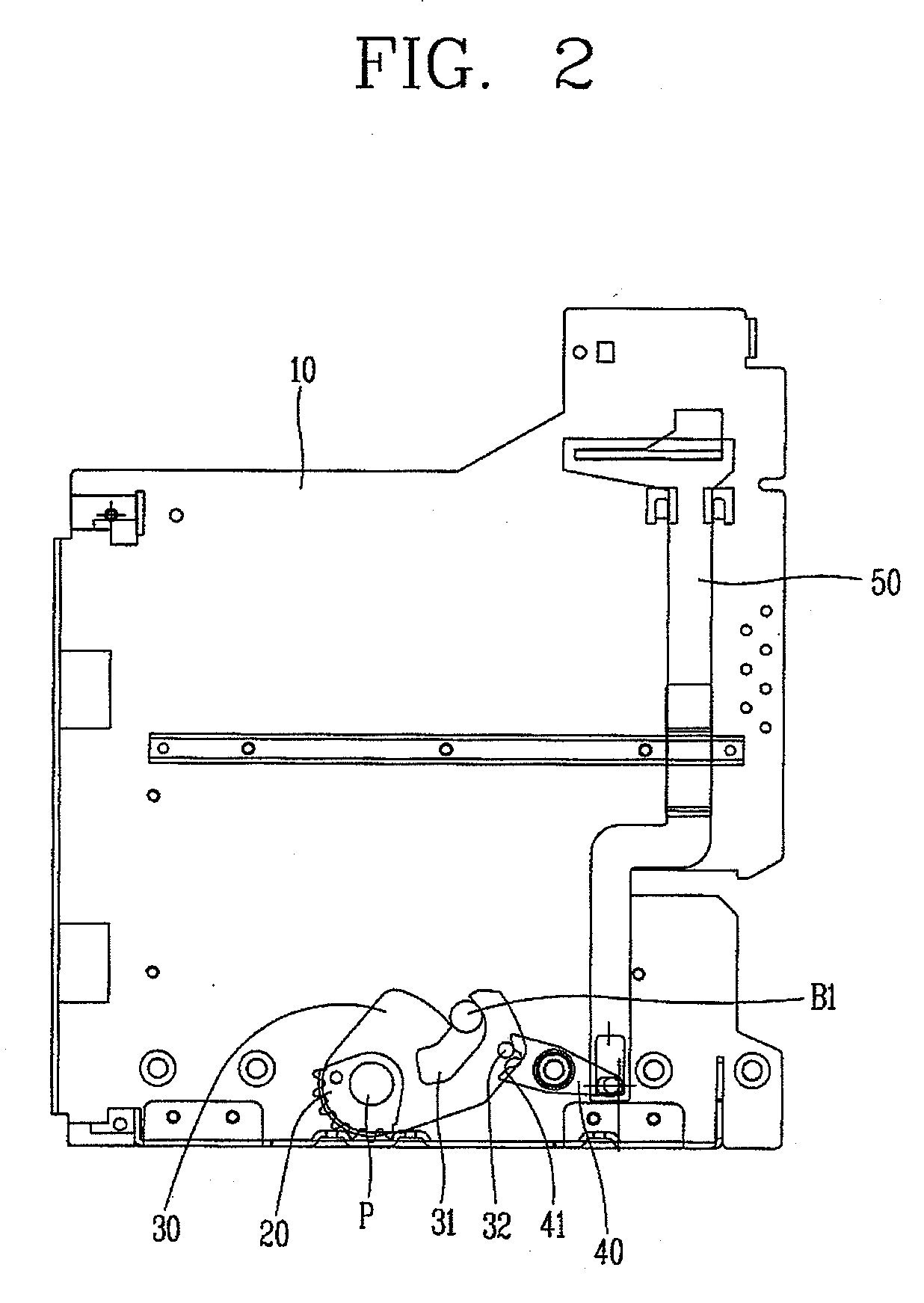
However, in the draw in-out apparatus for the air circuit breaker in the related art, since a distance d1 between the reaction point RP of the reaction force and the pivot P of the cam 30 is long, as the air circuit breaker has larger capacity and size, it becomes to be more difficult for the cam 30 to endure the reaction force.
Further, as an air circuit breaker has larger capacity and size, a load of the main body is also increased.
Further, since the draw in-out apparatus for the air circuit breaker in accordance with the related art should endure the load of the main body and the reaction force by a rotation torque of a small pinion gear, the draw in-out apparatus having this structure cannot be applied to an air circuit breaker having large capacity and size.

Method used


Image

  • Draw in-out apparatus for air circuit breaker
  • Draw in-out apparatus for air circuit breaker
  • Draw in-out apparatus for air circuit breaker

Examples


Embodiment Construction

[0041]Description will now be given in detail of the preferred embodiments of the present invention, examples of which are illustrated in the accompanying drawings.

[0042]As shown in FIG. 4, an air circuit breaker in accordance with the present invention includes a main body 20 and a cradle 10. A reference character S1 referring a front lower portion of the main body 20 designates a handle connection portion of a spindle S, which is shown in FIG. 6 in detail.

[0043]As well-known and described above, the main body 20 includes a switching mechanism (not shown), contactors, an arc extinguishing mechanism, an electric terminal (refer to a reference character T2 in FIGS. 10 and 11) for being electrically connected to the cradle 10. The main body 20 is movable to a connected position for being electrically connected to the cradle 10, a test position at which the main body 20 is electrically disconnected from the cradle 10 but a control power source (i.e., an electrical power source for a co...


PUM


Abstract

Disclosed is a draw in-out apparatus that is suitable for an air circuit breaker having large capacity and size, the apparatus comprising: a movable plate meshed with the thread portion of a spindle so as to be movable back and forth; rack gear installed on the movable plate so as to be movable back and forth along with the movable plate moving back and forth; pinion gear installed to be meshed with the rack gear and rotatable according to the rack gear moving back and forth; a cam rotatable by a rotational driving force transferred from the pinion gear by being provided with a teeth portion meshed with the pinion gear and having a radius larger than those of the pinion gear so as to amplify a torque transferred from the pinion gear and provided with a cam slot portion for enduring a load of the main body and a reaction force generated when the main body and the cradle are electrically connected to each other while the main body is moved to a connected position; a pivot disposed on the cradle at a position adjacent to the middle of a height between electric terminals of the cradle so as for the cam to effectively endure the load of the main body and the reaction force generated when the main body and the cradle are electrically connected to each other; and a driving protruding portion extended from the main body with moving together with the main body and connected to the cam thus to transfer a driving force from the cam to the main body.

Description

BACKGROUND OF THE INVENTION[0001]1. Field of the Invention[0002]The present invention relates to an air circuit breaker, more particularly, to, in an air circuit breaker, a draw in-out apparatus for an air circuit breaker which is capable of stably enduring a load of a main body when performing a draw-in operation and a reaction force generated when an electric terminal of the main body and an electric terminal of a cradle are connected to each other.[0003]2. Description of the Related Art[0004]An air circuit breaker refers to an industrial circuit breaker for switching a circuit for a low voltage comparing with a vacuum circuit breaker for switching a circuit for a high voltage. The air circuit breaker mainly includes a main body and a cradle. Here, the main body includes a switching mechanism, contactors, an arc extinguishing mechanism and an electric terminal to be electrically connected with the cradle. The main body may be moved to a position for being electrically connected to...

Claims


Application Information

Patent Timeline
Patent Type & Authority Applications(United States)
IPC IPC(8): H02B11/127
CPCH02B11/127H01H3/3015H01H33/42H01H71/52H01H71/522
Inventor KIM, HYUN-JAENA, KI-CHULKIM, MYOUNG-SOOLYU, JAE-GOO
Owner LS IND SYETEMS CO LTD
Why Eureka
Try Eureka