Particulate collector for mixing container

Inactive Publication Date: 2009-01-15
BEATON JOEL S
View PDF30 Cites 12 Cited by
  • Summary
  • Abstract
  • Description
  • Claims
  • Application Information

AI Technical Summary

Benefits of technology

[0007]It is an object of the present invention t

Problems solved by technology

Several problems arise during the mixing process.
First when pouring the powder into the container, powde

Method used


Image

  • Particulate collector for mixing container
  • Particulate collector for mixing container
  • Particulate collector for mixing container

Examples


Embodiment Construction

[0024]The present invention will now be described in accordance with a preferred embodiment. As will become apparent to one skilled in the art many modifications, different shapes and sizes and different materials all lie within the spirit and scope of the present invention.

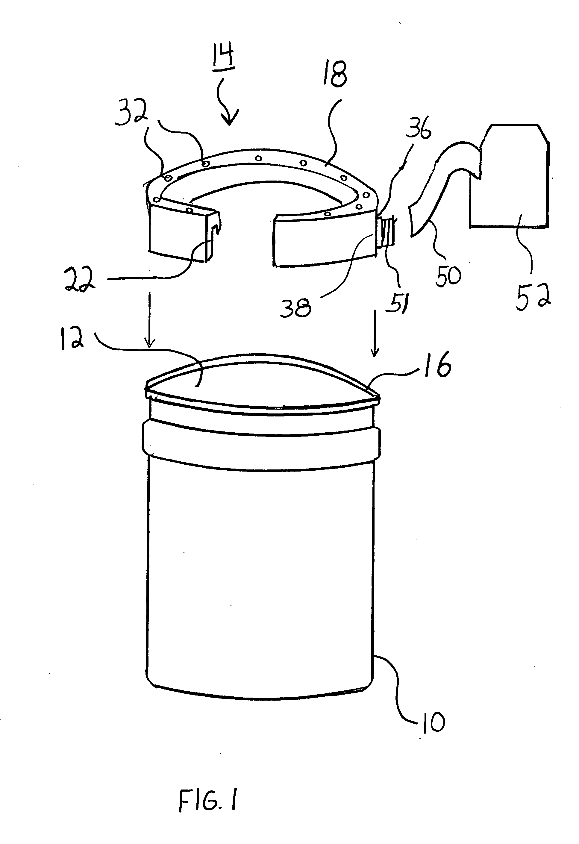
[0025]Turning now to FIG. 1, there is depicted a five gallon mixing container 10 which is often used to mix various masonry compounds such as mortar and grout. The five gallon mixing container 10 includes an interior surface 12 in which mixing is accomplished.

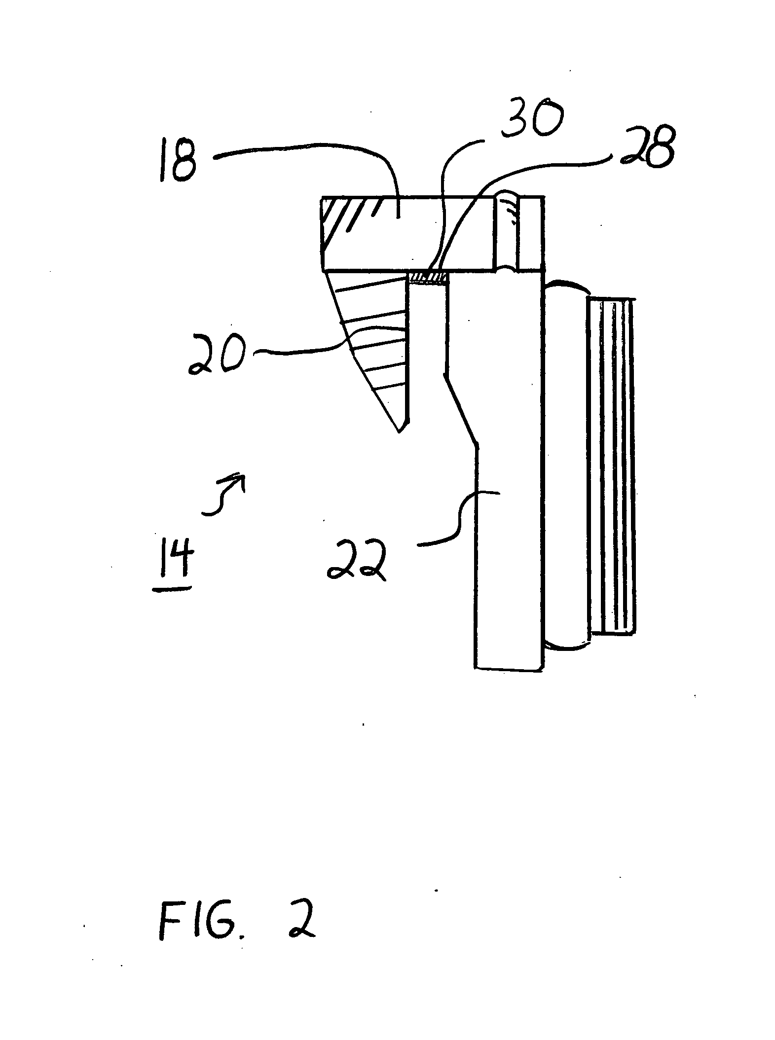
[0026]An annular particulate collecting ring 14, depicted in FIGS. 2 and 3, engages with a top annular surface 16 of the five gallon mixing container 10. In order to engage the top annular surface 16, the annular particulate collecting ring 14 includes a top annular member 18, an inner annular flange 20 which extends downwardly from the top annular member 18, and an outer annular chamber 22 which also extends downward from the top annular member 18.
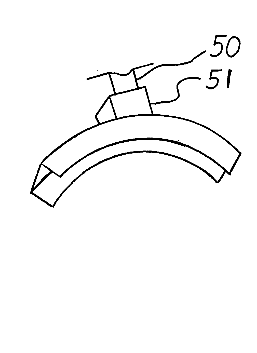
[0027]A b...


PUM

PropertyMeasurementUnit
Perimeteraaaaaaaaaa

Abstract

The present invention provides a particulate collection apparatus for use in mixing powdery substances such as mortar and grout into a paste like workable compound. The particulate collection apparatus engages a top surface of a mixing container. The particulate collection apparatus includes a plurality of equidistant spaced openings, preferably along its top surface which extend into a hollowed member. The hollowed member further includes an exteriorly situate opening which mates with a vacuum hose. As such the vacuum creates a downward draft that draws billowing particulates through the hollowed member and into a vacuum storage container.

Description

[0001]The present invention is a continuation in part application from the same inventor Ser. No. 11 / 827,071 which bears a filing date of Jul. 11, 2007 for which the benefit of the earlier priority date is herewith claimed under 35 USC 120.FIELD OF THE INVENTION[0002]The present invention relates generally to the field of masonry and, more particularly, to the field of mixing mortar and grout in a mixing container.BACKGROUND OF THE INVENTION[0003]In the tile setting and masonry trades it is always necessary to mix mortar and grouts for installation and replacement of tiles, bricks and the like. Mortar and grout are typically made by mixing powdery compound with a sufficient amount of water to create a paste like substance. The paste like substance is then applied with a trowel or other tool either to secure the tile or brick or to fill in a gap between the same.[0004]The mixing typically takes place in a portable container, such as a five gallon bucket. The user first pours the powd...

Claims


Application Information

Patent Timeline
IPC IPC(8): B01F13/06
CPCB01F15/00954B28C5/0806B08B15/007B01F15/00961B01F35/184B01F35/181
Inventor BEATON, JOEL S.
Owner BEATON JOEL S
Why Eureka
Try Eureka