
Defective pixel detector, imaging device, and defective pixel detection method

Inactive Publication Date: 2009-01-15
ELMO CO LTD
View PDF1 Cites 16 Cited by
  • Summary
  • Abstract
  • Description
  • Claims
  • Application Information

AI Technical Summary

Benefits of technology

[0011]The defective pixel detector according to one aspect of the invention successively obtains the pixel data representing the pixel value of the target pixel set as the object of defective pixel detection and the pixel data representing the pixel values of the plural surrounding peripheral pixels located in the neighborhood of the target pixel. The number of pixel data obtained may be set arbitrarily. For example, in a matrix arrangement of multiple light receiving elements included in an image sensor mounted on the imaging device, the defective pixel detector may successively obtain pixel data of each 5×5 pixel block including a target pixel on its center. The defective pixel detector subsequently calculates the absolute values of the differences between the pixel values of the multiple specific peripheral pixels selected among the plural surrounding pixels as the first absolute values, and sets the defective pixel criterion, which is used in subsequent identification of whether the target pixel is a defective pixel, based on the differences between the multiple first absolute values and the preset threshold value. The multiple specific peripheral pixels and the preset threshold value may be set arbitrarily according to the arrangement of the light receiving elements in the image sensor and according to the presence or the absence of color filters set on the respective light receiving elements. This enables the defective pixel criterion to be set adequately according to the potential for recognition of the target pixel as a defective pixel. The defective pixel detector then calculates the absolute values of the differences between the pixel value of the target pixel and the pixel values of the multiple specific peripheral pixels as the second absolute values, and identifies whether the target pixel is a defective pixel, based on the multiple second absolute values and the set defective pixel criterion. The defective pixel detector of this arrangement mounted on the imaging device equipped with the image sensor determines whether each of the target pixels has a high potential for recognition as a defective pixel or a low potential for recognition as a defective pixel in the imaging process and successively and accurately identifies whether each of the target pixels is a defective pixel, based on the results of the determination.
[0031]In the imaging device of this application, the pixel data correction unit readily corrects the pixel data of the detected defective pixel. The correction of the pixel data of the defective pixel may replace the pixel data of the defective pixel by a weighted average of the pixel values of the multiple specific peripheral pixels, instead of the simple average of the pixel values of the multiple specific peripheral pixels.

Problems solved by technology

In display of an image taken with the imaging device on a display device, malfunction of any light receiving element in the imaging process may cause output of pixel data having a higher pixel value than an originally expected pixel value.
Malfunction of any light receiving element in the imaging process may otherwise cause output of pixel data having a lower pixel value than the originally expected pixel value.
The proposed prior art techniques of Japanese Patent Laid-Open No. 2001-86517 and No. 2002-344814 are, however, not sufficient for accurate detection of defective pixels.

Method used


Image

  • Defective pixel detector, imaging device, and defective pixel detection method
  • Defective pixel detector, imaging device, and defective pixel detection method
  • Defective pixel detector, imaging device, and defective pixel detection method

Examples


first embodiment

A. First Embodiment

A1. Structure of Imaging Device

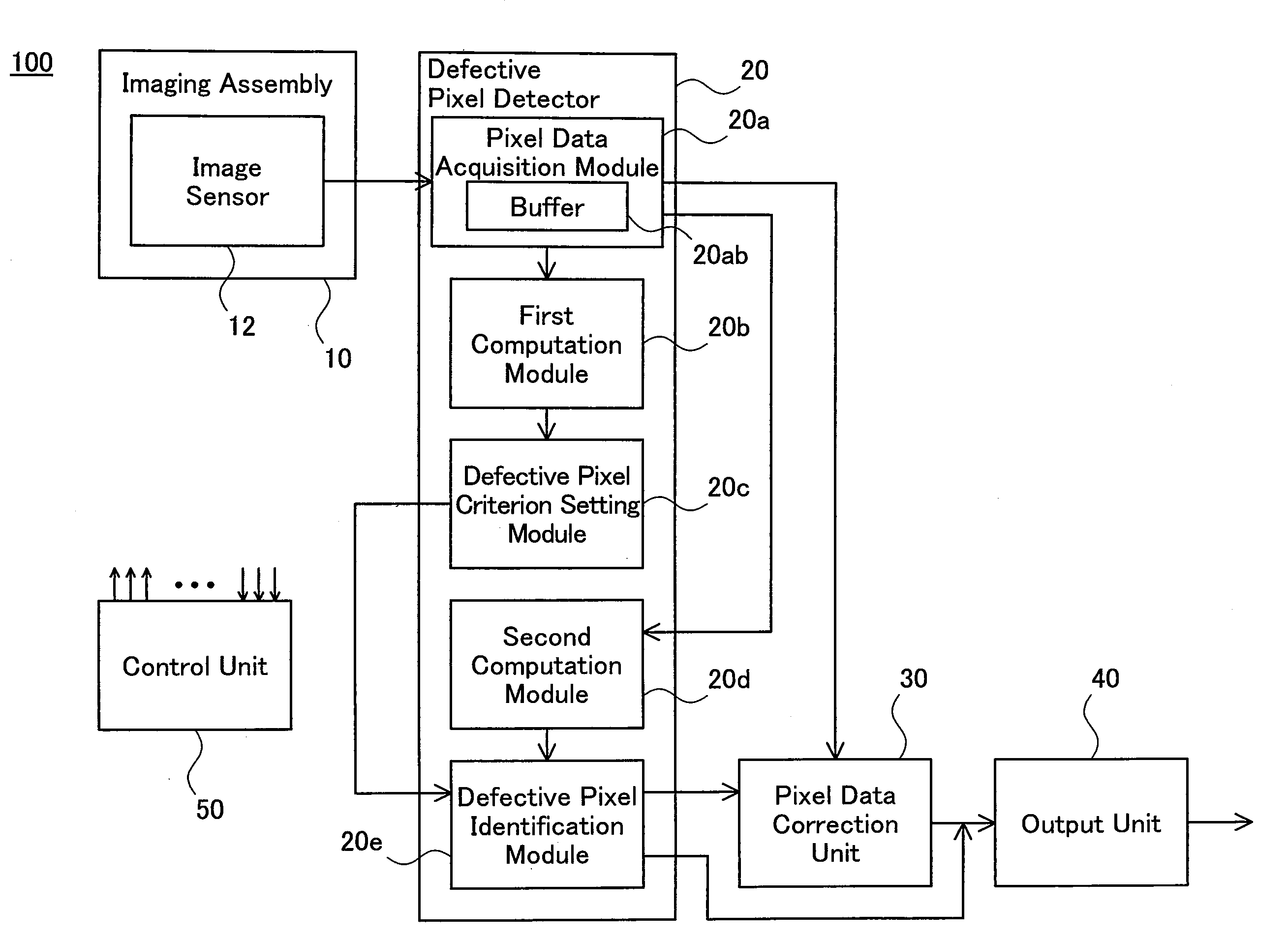
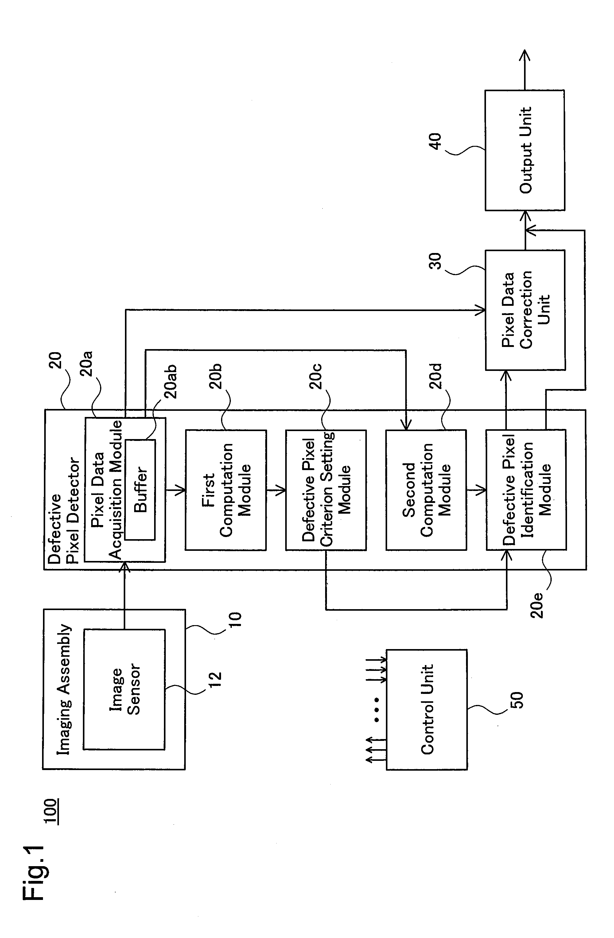
[0053]FIG. 1 schematically illustrates the structure of an imaging device 100 in a first embodiment of the invention. The imaging device 100 includes an imaging assembly 10, a defective pixel detector 20, a pixel data correction unit 30, and an output unit 40. The imaging device 100 successively detects defective pixels (white defects and black defects) among multiple pixels constituting an image taken with the imaging assembly 10, corrects pixel data of the detected defective pixels, and outputs the corrected pixel data as explained below. The defective pixel detector 20, the pixel data correction unit 30, and the output unit 40 are configured by the hardware in this embodiment, although some part of these constituents may be implemented by the software configuration. The imaging device 100 also includes a display unit constructed to display the taken image, for example, a liquid crystal panel, and a recorder unit constructed to sto...

second embodiment

B. Second Embodiment

B1. Structure of Imaging Device

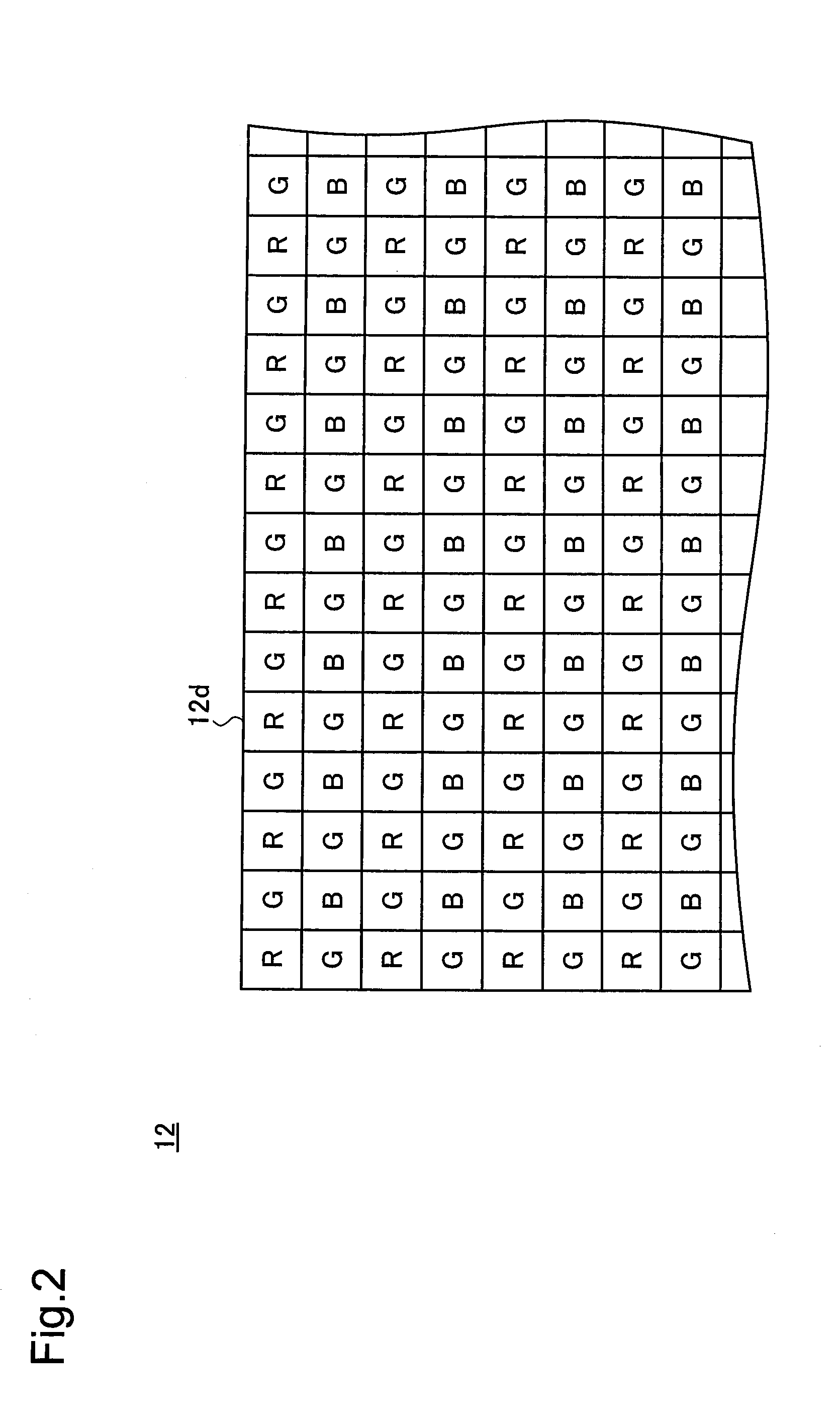
[0111]FIG. 9 schematically illustrates the structure of another imaging device 100A in a second embodiment of the invention. The imaging device 100A of the second embodiment has an imaging assembly 10A of a three-plate type including three image sensors 12R, 12G, and 12B, for example, CMOS sensors. The imaging assembly 10A has a light color separation optical system, in addition to the zoom lens, the focusing lens, and the aperture mechanism included in the imaging assembly 10 of the first embodiment. The light color separation optical system includes a prism arranged to separate the incident light entering via the zoom lens, the focusing lens, and the aperture mechanism into three color lights red (R), green (G), and blue (B). The image sensors 12R, 12G, and 12B respectively generate red (R) pixel data, green (G) pixel data, and blue (B) pixel data. Each of the image sensors 12R, 12G, and 12B has multiple light receiving elements a...

modified example 1

C1. Modified Example 1

[0125]In the procedure of the first embodiment, the defective pixel criterion setting module 20c sets the defective pixel criterion Vjth(R) for the red (R) target pixel Rt to the threshold value Vjth1(R) when at least one of the multiple absolute values Vabs1(R) is not less than the preset threshold value Vth(R), while setting the defective pixel criterion Vjth(R) to the threshold value Vjth2(R) when all the multiple absolute values Vjth(R) are less than the preset threshold value Vth(R). This arrangement is, however, neither essential nor restrictive. In one modified procedure, the defective pixel criterion setting module 20c may set the defective pixel criterion Vjth(R) to the threshold value Vjth1(R) when all the multiple absolute values Vabs1(R) are not less than the preset threshold value Vth(R), while setting the defective pixel criterion Vjth(R) to the threshold value Vjth2(R) when at least one of the multiple absolute values Vjth(R) is less than the pre...


PUM


Abstract

In a defective pixel detector 20 mounted on an imaging device 100, a pixel data acquisition module 20a successively obtains pixel data of a target pixel set as an object of defective pixel detection and pixel data of plural surrounding pixels located in a neighborhood of the target pixel. A first operation module 20b calculates absolute values of differences between pixel data of multiple specific peripheral pixels selected among the plural surrounding pixels, as first absolute values. A defective pixel criterion setting module 20c sets a defective pixel criterion, based on differences between the multiple first absolute values and a preset threshold value. A second operation module 20d calculates absolute values of differences between the pixel data of the target pixel and the pixel data the multiple specific peripheral pixels, as second absolute values. A defective pixel identification module 20e identifies whether the target pixel is a defective pixel, based on the multiple second absolute values and the set defective pixel criterion. This arrangement enables successive and accurate detection of defective pixels in the imaging process.

Description

BACKGROUND OF THE INVENTION[0001]1. Field of the Invention[0002]The present invention relates to a defective pixel detector mounted on an imaging device, and more specifically pertains to a technique of detecting defective pixels caused by, for example, malfunction of an image sensor included in the imaging device, among multiple pixels constituting an image taken by the imaging device.[0003]2. Description of the Related Art[0004]Various imaging devices including digital still cameras and digital video cameras have become popular and been widely used. The imaging device is equipped with an image sensor designed to convert light received via lenses into electrical signals. A CCD (charge coupled device) sensor and a CMOS (complementary metal oxide semiconductor) sensor are typical examples adopted for the image sensor. The image sensor includes multiple light receiving elements (photodiodes) provided corresponding to multiple pixels constituting a taken image and arranged to respectiv...

Claims


Application Information

Patent Timeline
IPC IPC(8): G06K9/40H04N5/335H04N5/367H04N5/372H04N5/374H04N5/376H04N5/378
CPCG09G2330/08G09G2360/147H04N9/07H04N9/045H04N5/3675H04N25/683H04N23/12H04N25/134
Inventor NAGATSUMA, HIROSHIMASUI, YASUONAKAMURA, TADAMASANISHIWAKI, KATSUHIRO
Owner ELMO CO LTD
Features
  • Generate Ideas
  • Intellectual Property
  • Life Sciences
  • Materials
  • Tech Scout
  • Unparalleled Data Quality
  • Higher Quality Content
  • 60% Fewer Hallucinations
Learn More