
Image forming apparatus, scanning optical apparatus, and control methods thereof

a technology of scanning optical apparatus and image forming apparatus, applied in the direction of electrographic process apparatus, optics, instruments, etc., can solve the problems of long control time, poor tone reproduction capability in low density portions, and long drive current, and achieve suppressing an increase in control time and high accuracy

Inactive Publication Date: 2009-01-15
CANON KK
View PDF6 Cites 8 Cited by
  • Summary
  • Abstract
  • Description
  • Claims
  • Application Information

AI Technical Summary

Benefits of technology

[0007]The present invention enables realization of an image forming apparatus that adjusts the amount of light of a light-emitting unit with high accuracy and suppresses an increase in control time that is required to adjust the amount of light, a scanning optical apparatus and control methods thereof.

Problems solved by technology

However, it has poor tone reproduction capability in low density portions.
As a result, if fogging is found, it is necessary to set the drive current again.
However, this method also requires several times of setting and checking of a D / A for the drive current for low density portions.
As described above, the conventional technology requires several times of setting of the drive current to reproduce a density tone with high accuracy, which involves a long control time.

Method used


Image

  • Image forming apparatus, scanning optical apparatus, and control methods thereof
  • Image forming apparatus, scanning optical apparatus, and control methods thereof
  • Image forming apparatus, scanning optical apparatus, and control methods thereof

Examples


Embodiment Construction

[0023]A preferred embodiment of the present invention will now be described in detail with reference to the drawings. It should be noted that the relative arrangement of the components, the numerical expressions and numerical values set forth in these embodiments do not limit the scope of the present invention unless it is specifically stated otherwise.

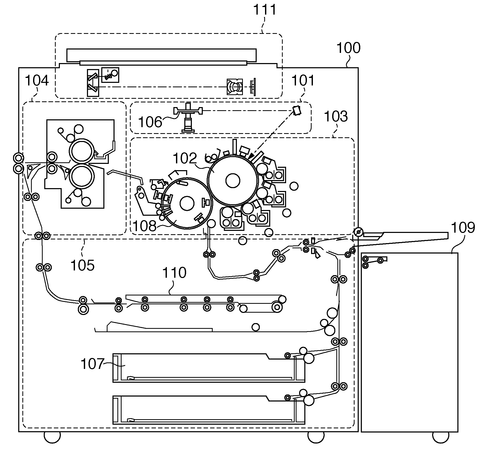
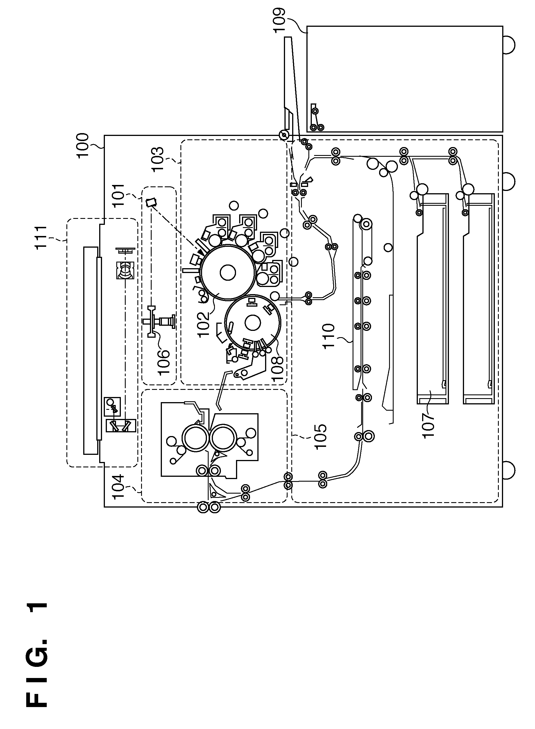
[0024]Hereinafter, an embodiment of the present invention will be described with reference to FIGS. 1 to 6B. FIG. 1 is a cross-sectional view illustrating the overall configuration of a printer 100 according to an embodiment of the present invention. Here, an electrophotographic printer 100 will be described as an example of an image forming apparatus.

[0025]The printer 100 includes a scanner unit 111, a laser exposure unit 101, an image forming unit 103, a fixing unit 104, a paper feed / transport unit 105, and a printer control unit (not shown) that controls these units.

[0026]The scanner unit 111 irradiates light onto an original docum...


PUM


Abstract

The present invention provides an image forming apparatus that adjusts the amount of light of a light-emitting unit with high accuracy and suppresses an increase in control time that is required to adjust the amount of light, a scanning optical apparatus, and control methods thereof. To accomplish this, the image forming apparatus of the present invention derives a threshold current and a bias current of the light-emitting unit. Further, the image forming apparatus of the present invention supplies the bias current to the light-emitting unit when causing the light-emitting unit to emit light in an amount of light corresponding to the minimum density level, and supplies a current that is larger than the threshold current to the light-emitting unit when causing the light-emitting unit to emit light in an amount of light corresponding to a density level that is larger than that minimum density level.

Description

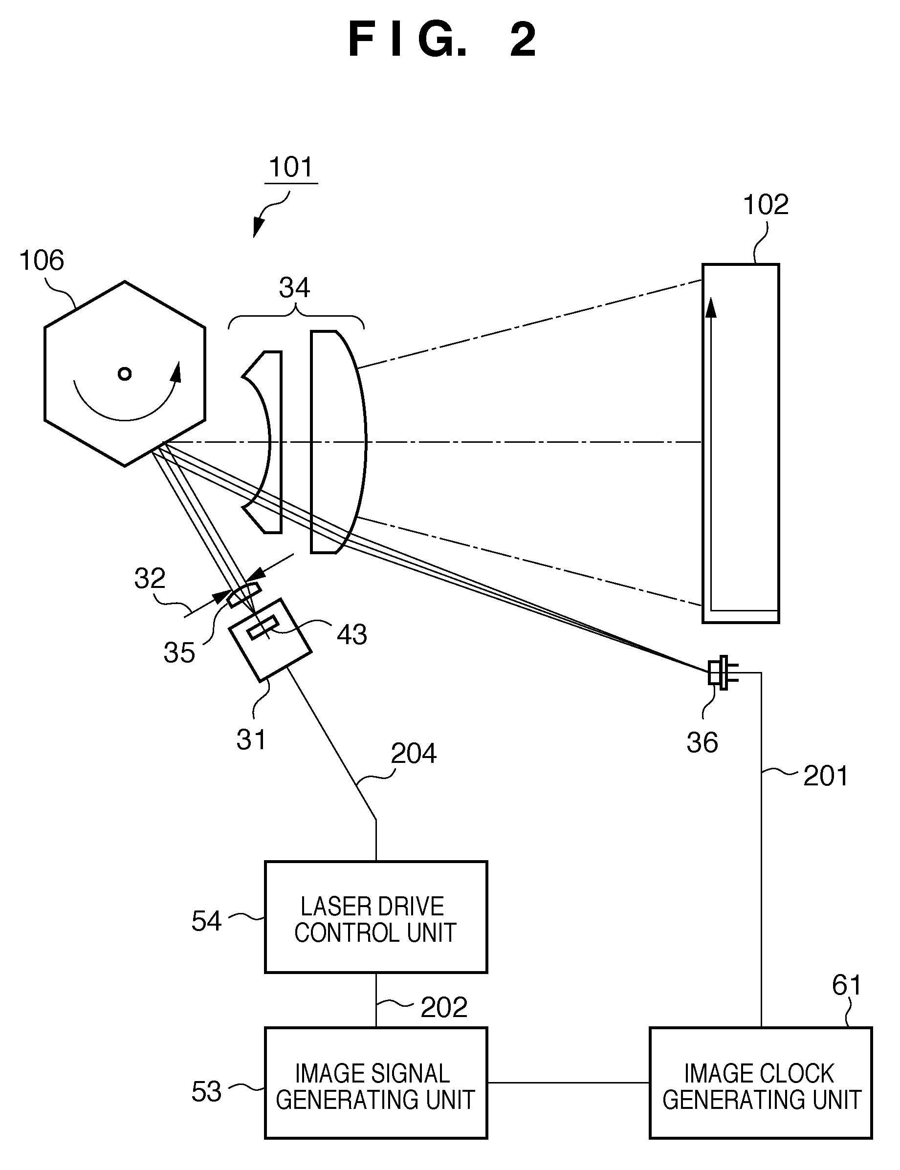
BACKGROUND OF THE INVENTION[0001]1. Field of the Invention[0002]The present invention relates to an image forming apparatus that includes a scanning optical apparatus for forming an electrostatic latent image on a photosensitive member, a scanning optical apparatus, and control methods thereof.[0003]2. Description of the Related Art[0004]Electrophotographic image forming apparatuses typically include a scanning optical apparatus for forming an electrostatic latent image on a photosensitive member. The scanning optical apparatus includes a semiconductor laser for irradiating light, and adjusts the density of images to be formed by adjusting the intensity (amount) of light that is irradiated. Ordinarily, when a current input to a semiconductor laser reaches a given level, the amount of light starts to show a stable increase. Hereinafter, this given current is referred to as “threshold current”. According to conventional technology, the amount of light is increased proportionally to th...

Claims


Application Information

Patent Timeline
Patent Type & Authority Applications(United States)
IPC IPC(8): G03G15/04
CPCG03G15/043G03G15/0435G03G2215/0404
Inventor KOGA, KATSUHIDE
Owner CANON KK
Learn More