
A Variable Chain Length Dynamic Boundary Scan Structure and Method Based on Switch Matrix Control

A boundary scan and switch matrix technology, applied in the field of variable chain length dynamic boundary scan structure, can solve the problem that the length of the boundary scan chain is fixed, the shift period is long, and it cannot better adapt to the real-time and dynamic requirements of health management. and other problems to achieve the effect of improving efficiency and corresponding time, fast capture and transmission

Active Publication Date: 2017-12-01
NO 771 INST OF NO 9 RES INST CHINA AEROSPACE SCI & TECH
View PDF6 Cites 0 Cited by
  • Summary
  • Abstract
  • Description
  • Claims
  • Application Information

AI Technical Summary

Problems solved by technology

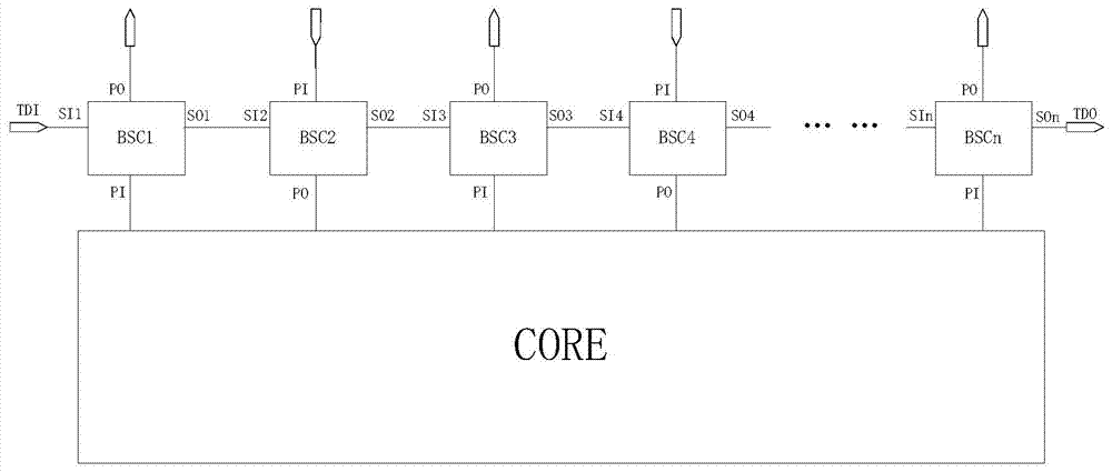
[0003] However, at present, the internal boundary scan structure of most design circuits is determined, both the order of the boundary scan cells and the length of the boundary scan chain are fixed.
Such a boundary-scan structure is easily limited by the number and location of pins in application. The pin information near the serial output port is easy to be sampled, and the pin information near the serial input port needs to be sampled after a long period of time. Shifting can only be obtained, resulting in a long shifting cycle and low efficiency, which cannot better adapt to the real-time and dynamic requirements of health management and information collection

Method used


Image

  • A Variable Chain Length Dynamic Boundary Scan Structure and Method Based on Switch Matrix Control
  • A Variable Chain Length Dynamic Boundary Scan Structure and Method Based on Switch Matrix Control
  • A Variable Chain Length Dynamic Boundary Scan Structure and Method Based on Switch Matrix Control

Examples


Embodiment Construction

[0039] The present invention will be further described in detail below in conjunction with specific embodiments, which are explanations of the present invention rather than limitations.

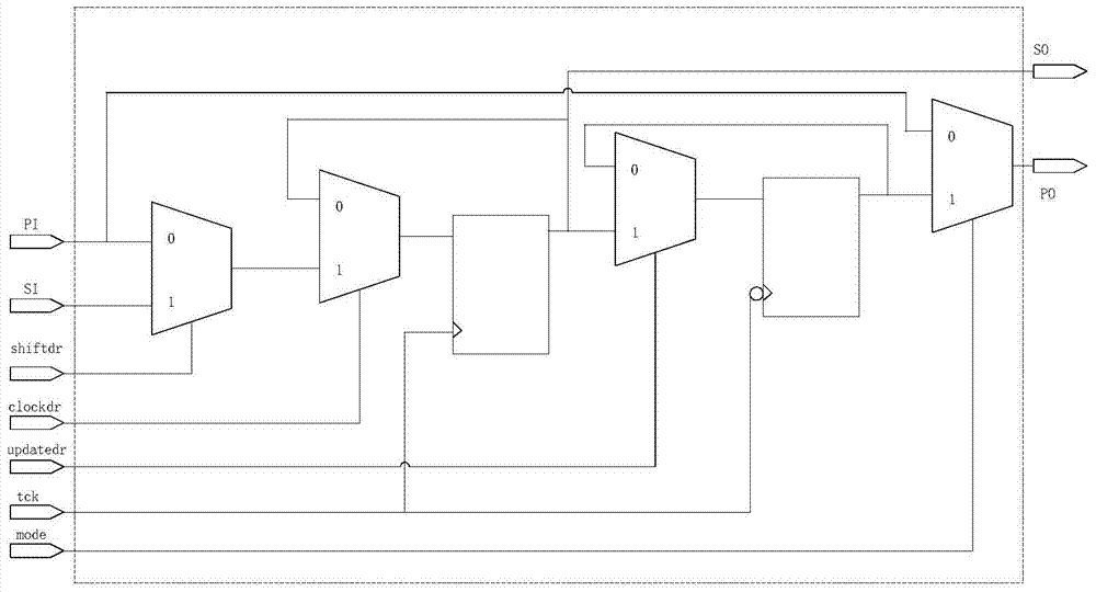
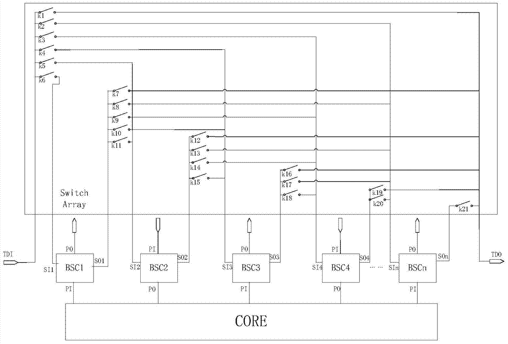
[0040] The present invention designs a switch control matrix based on the variable chain length dynamic boundary scan structure and method of switch matrix control. The output end of is the serial input end of all side scan units. After the control of the switch matrix is ​​started, the switch matrix will assemble the scan chain according to the set target, connect the pins to be observed in series in a certain order to form the target scan chain, and use it to capture and transmit the required data information. This process is like turning a switch, and the formed target chain is a high-speed railway quickly assembled according to needs. The control logic of the switch matrix can be configured through registers, and can also be realized through decoding logic. The structure of this part is ...


PUM


Abstract

The present invention is based on the variable chain length dynamic boundary scan structure and method of switch matrix control, and through the switch control matrix composed of switches corresponding to each boundary scan unit, it can perform the most optimal operation when performing boundary scan units with different numbers and positions. Optimized switch and link control form a highly efficient boundary scan short chain to complete the scheduled scan target. At the same time, structurally, the input of the matrix is ​​the control logic of the switch matrix and the serial output of all side-scan units, while the output of the switch matrix is ​​the serial input of all side-scan units. After the control of the switch matrix is ​​started, the switch matrix will assemble the scan chain according to the set target, and connect the pins to be observed in series in a certain order to form the target scan chain, which is used to quickly capture and transmit the required data information ; Compared with the link scanning structure and method in the prior art, the cycle number that can be saved can reach more than 90%, the efficiency is extremely high, and the response is fast.

Description

technical field [0001] The invention relates to circuit boundary scan, in particular to a variable chain length dynamic boundary scan structure and method based on switch matrix control. Background technique [0002] Boundary scan technology is widely used in many fields such as computer, communication and aerospace because of its high flexibility and good integration. Boundary scan enables many system functions such as online "health" monitoring, information gathering, fault detection, fault injection (for failover testing or redundancy testing), and diagnostics. As far as health management and information collection are concerned, the real-time or dynamic requirements for chips or systems are high, which requires boundary scan to have better adaptability to this. [0003] However, at present, the internal boundary scan structure of most design circuits is determined, and both the order of the boundary scan cells and the length of the boundary scan chain are fixed. Such a...

Claims


Application Information

Patent Timeline
Patent Type & Authority Patents(China)
IPC IPC(8): G01R31/28
Inventor 刘才强沈拉民韦超
Owner NO 771 INST OF NO 9 RES INST CHINA AEROSPACE SCI & TECH
Learn More