Blind rivet in particular for fixing a structure and method for inserting same

a technology of fixing structure and blind rivets, which is applied in the direction of threaded fasteners, fastening means, dowels, etc., can solve the problems of requiring more material, requiring the manufacture and management of rivets comprising three elements, and not avoiding the final breaking of bulbs into two parts, etc., and achieves constant height

Inactive Publication Date: 2009-01-15
ATELIERS DE LA HAUTE GARONNE ETS AURIOL & CIE +2
View PDF3 Cites 9 Cited by
  • Summary
  • Abstract
  • Description
  • Claims
  • Application Information

AI Technical Summary

Benefits of technology

[0022]prolonging the force having the effect of bringing the two support surfaces closer together and consequently bringing closer together the two elements to be assembled.
[0024]This rivet is particularly advantageous in that it offers an enlarged support surface, as a result of the opening out, for transmission of the pulling force which contributes towards better clamping by the mandrel. This mandrel is preformed with a plurality of serrations onto which the head of the sleeve is crimped which contributes towards maintenance of the clamping by the mandrel.
[0036]In the invention, the displacement of the mandrel depends on the thickness to be clamped, which makes it possible to obtain good crimping irrespective of where located in the clamping range of the fixing. The breaking before opening out defined by the wording of the first claim plays a part in maintaining the height of the movable part of the sleeve by avoiding any deformation before breaking. Moreover, in the invention, the deformation following breaking is only an opening out around the stationary part and does not require a consequent bending liable to modify the height of the movable part or make the limit of resistance to elastic deformation thereof be exceeded. Crimping is carried out before the pulling force exceeds the limit of resistance to elastic deformation of the opened-out movable part and therefore before this part varies in height.
[0037]The breaking before opening out also avoids too great an amplitude of deformation before clamping, an amplitude which would have as a consequence the formation of cracks in the metal. Thus, another object of the invention relates to a fitting method which is remarkable in that it consists of providing the breaking of the sleeve into two parts before starting the expansion of the movable part.

Problems solved by technology

The main drawback of this type of rivet is that it requires the manufacture and management of a rivet comprising three elements.
The main drawback of the bending technique is not avoiding the final breaking of the bulb into two parts and requiring more material.

Method used


Image

  • Blind rivet in particular for fixing a structure and method for inserting same
  • Blind rivet in particular for fixing a structure and method for inserting same
  • Blind rivet in particular for fixing a structure and method for inserting same

Examples


Embodiment Construction

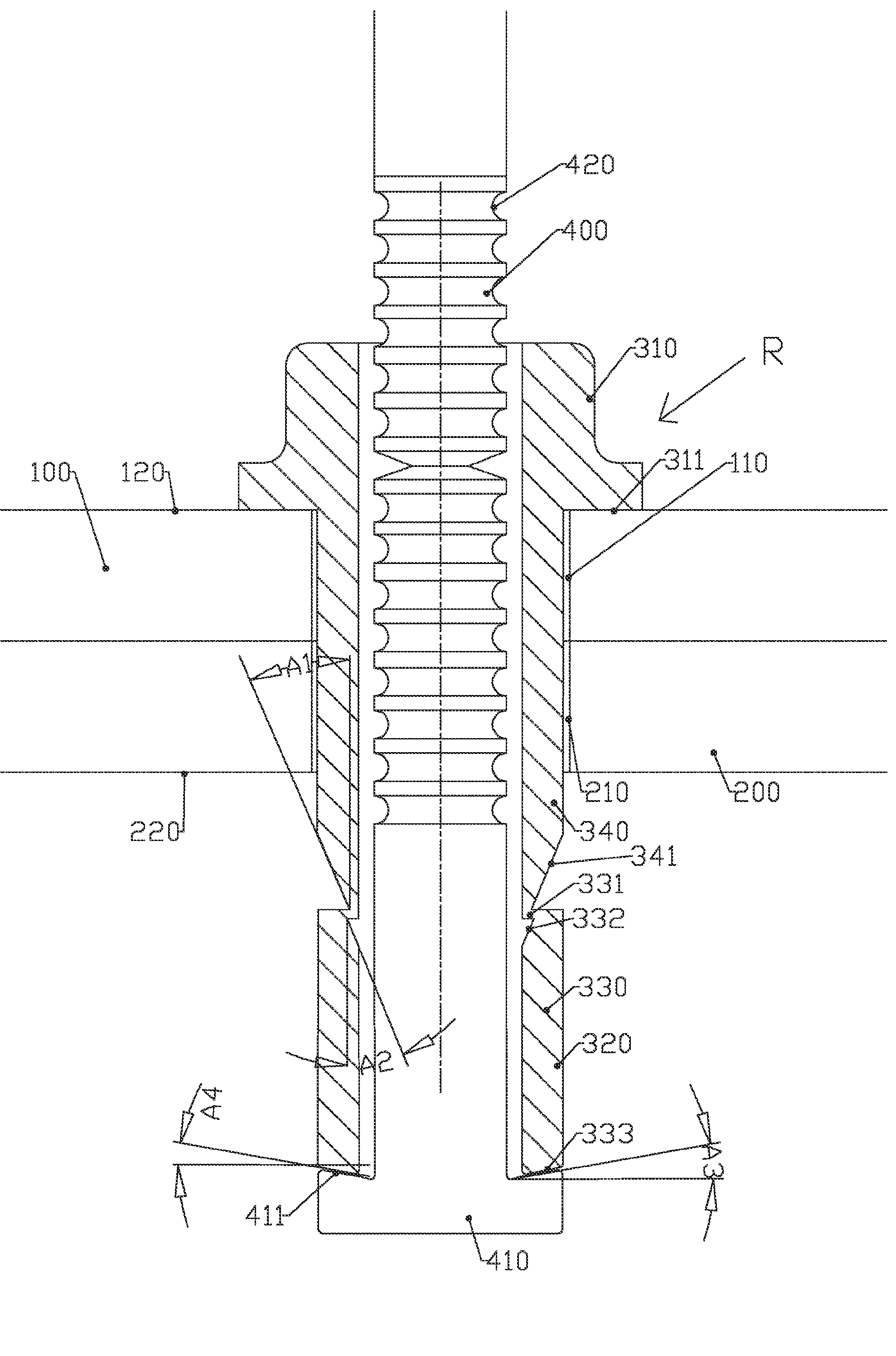
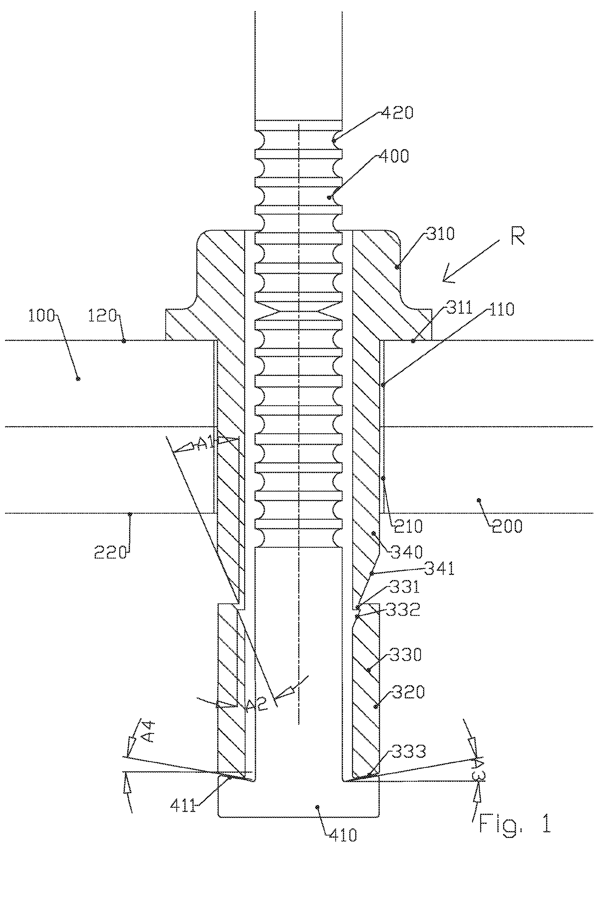
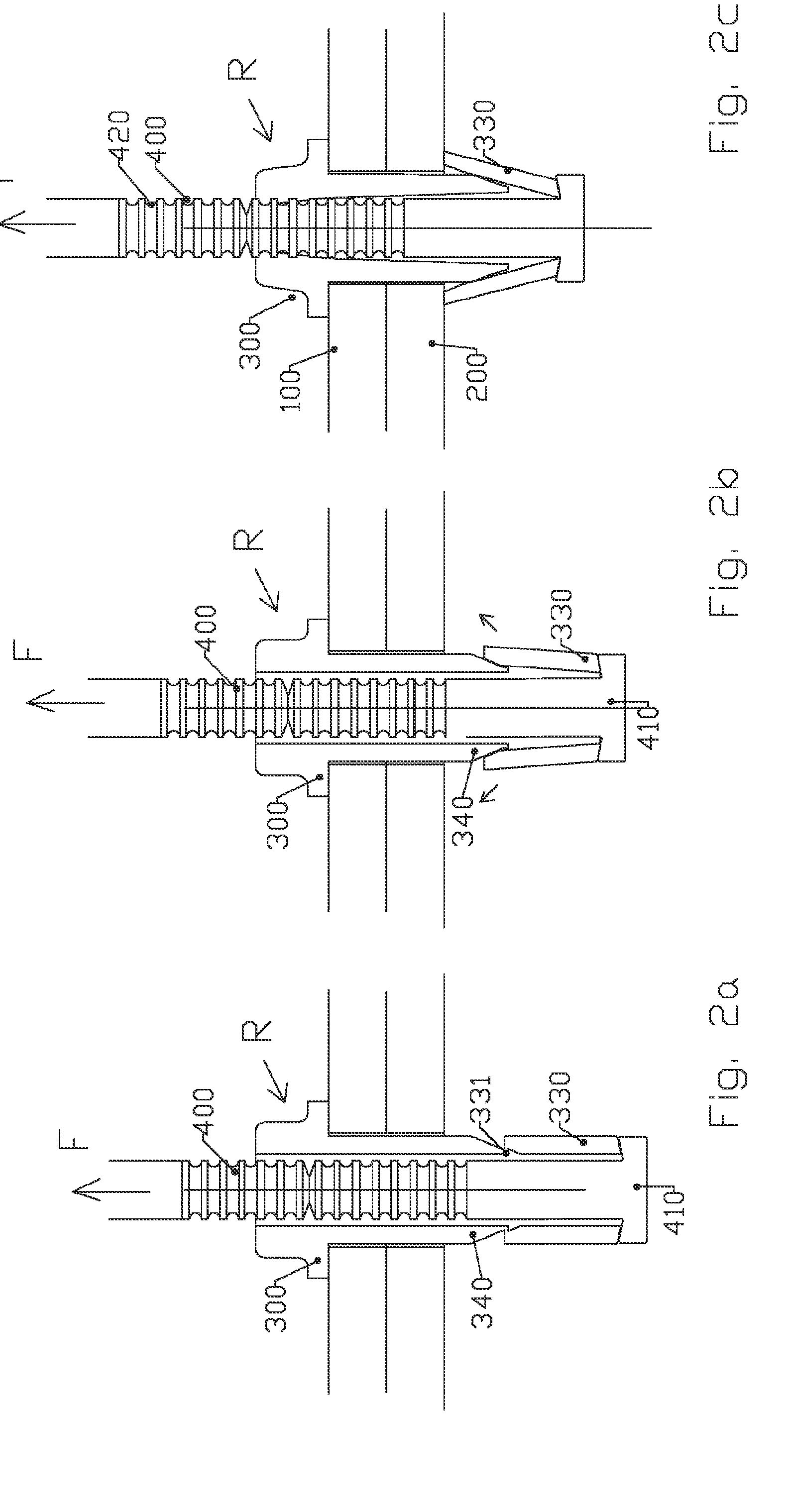
[0016]Starting from this established fact, the applicants carried out research aimed at proposing a blind rivet capable of solving the problems of distribution of the clamping forces by equipping the blind rivet with an improved sleeve which, under the action of the pulling force generated by the mandrel, deforms to offer a larger contact surface of the bulb with the metal sheet.

[0017]The blind rivet of the invention is of the type of that consisting of a deformable sleeve accommodating a divisible mandrel,

[0018]the assembly thus formed being positioned and passing through the apertures made substantially coaxial and formed in at least two elements to be assembled,

[0019]the sleeve comprising two ends:

[0020]a first end comprising a preformed head for defining a first support surface on the external surface of a first element, and

[0021]a second end which, under the action of deformation by pulling on the mandrel, comes to define a second support surface on the external surface of the ...


PUM


Abstract

The invention concerns a blind rivet (R) of the type consisting of a deformable bushing (300) and a cleavable mandrel (400), the thus formed assembly being urged to be positioned and pass through the orifices (110 and 120) made substantially coaxial and provided in at least two elements (100 and 200) to be assembled. Said rivet is characterized in that the bushing (300) consists of one single piece but preformed to have a second end (320) in two parts (330 and 340) which, under the action of an axial load (arrow F), are cleaved apart so that one part of the bushing (330) moved by the tensile load of the mandrel (400) is urged to be opened around the fixed part of the bushing (340), the expansion of the mobile part (330) called sleeve being produced without folding. The invention also concerns a method for inserting such a rivet. The invention is applicable to rivet fixing.

Description

FIELD OF APPLICATION OF THE INVENTION[0001]The present invention relates to the field of blind rivet type fixings and in particular to the adaptations making it possible to distribute the clamping forces of these rivets under the best conditions.DESCRIPTION OF THE PRIOR ART[0002]Conventionally, a blind rivet comprises a tubular sleeve and a pulling mandrel passing through said sleeve. The rivet is placed in a hole passing through the elements to be assembled. The sleeve comprises on a first end a head leaning on a first element. The sleeve comprises a second, non-shouldered, end that extends beyond the second element.[0003]Pulling the mandrel provides deformation of the non-shouldered end of the sleeve so as to clamp the elements between the shoulder of the sleeve and its deformed end (bulb). The surface area of the bulb in contact with the second element determines the distribution of the clamping forces of the rivet on the elements to be assembled.[0004]Enlarging this contact surf...

Claims


Application Information

Patent Timeline
Patent Type & Authority Applications(United States)
IPC IPC(8): F16B19/10
CPCF16B19/1063
Inventor AURIOL, PIERREAURIOL
Owner ATELIERS DE LA HAUTE GARONNE ETS AURIOL & CIE
Why Eureka
Try Eureka