Oil well pump apparatus

a technology for oil wells and pump apparatuses, which is applied in the direction of machines/engines, liquid fuel engines, borehole/well accessories, etc., can solve the problems of maintenance and repair that must be performed from time to tim

Inactive Publication Date: 2009-01-15
DAVIS RAYMOND C
View PDF8 Cites 26 Cited by
  • Summary
  • Abstract
  • Description
  • Claims
  • Application Information

AI Technical Summary

Benefits of technology

[0008]The present invention provides an improved pumping system from pumping oil from a well that provides a downhole pump apparatus that is operated with a working fluid that operates a specially configured pumping arrangement that includes a common shaft. One end portion of the shaft is a gerotor that is driven by...

Problems solved by technology

One of the problems with pumps is the maintenanc...

Method used


Image

  • Oil well pump apparatus
  • Oil well pump apparatus
  • Oil well pump apparatus

Examples


Embodiment Construction

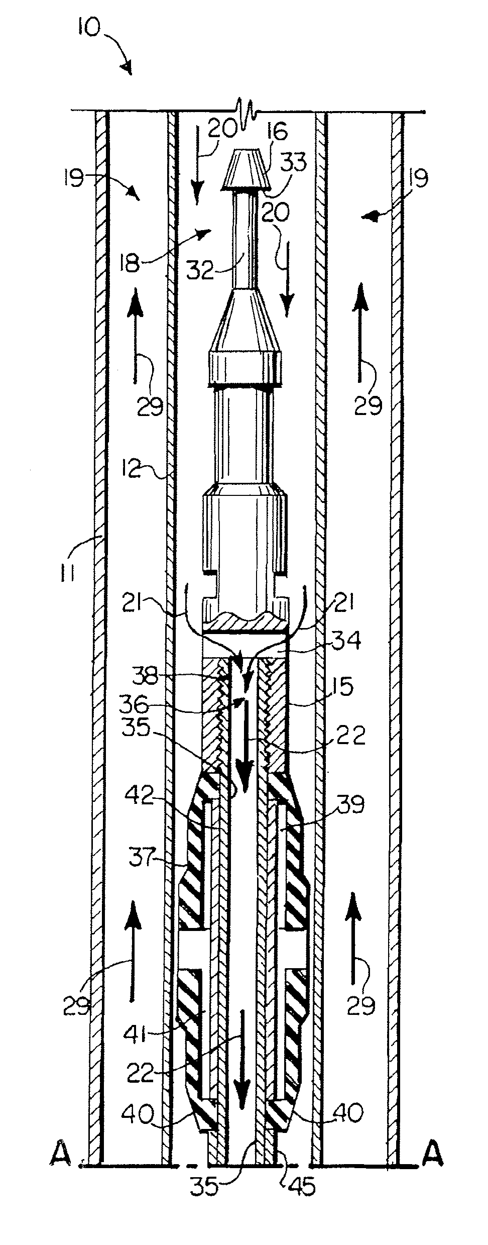
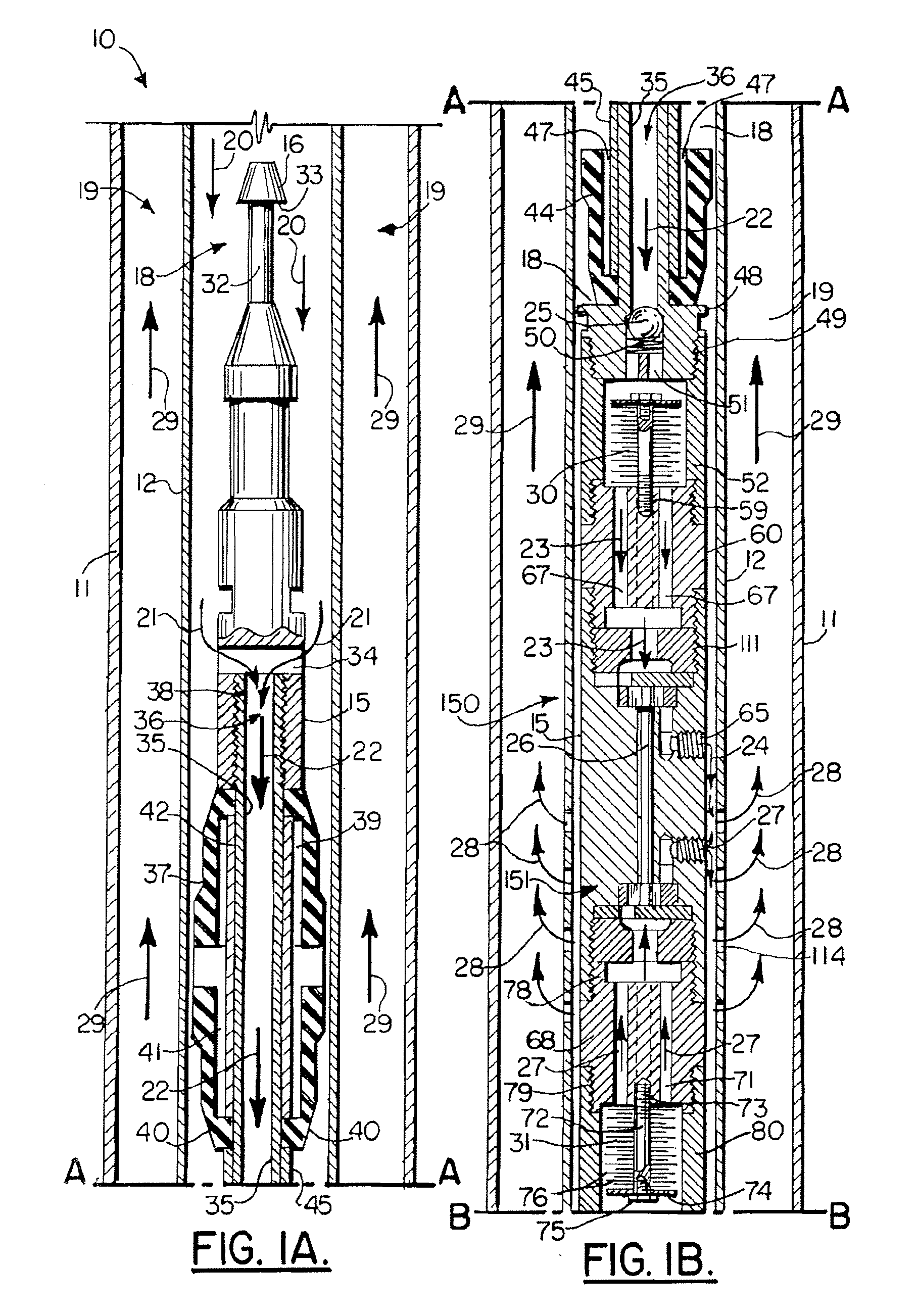
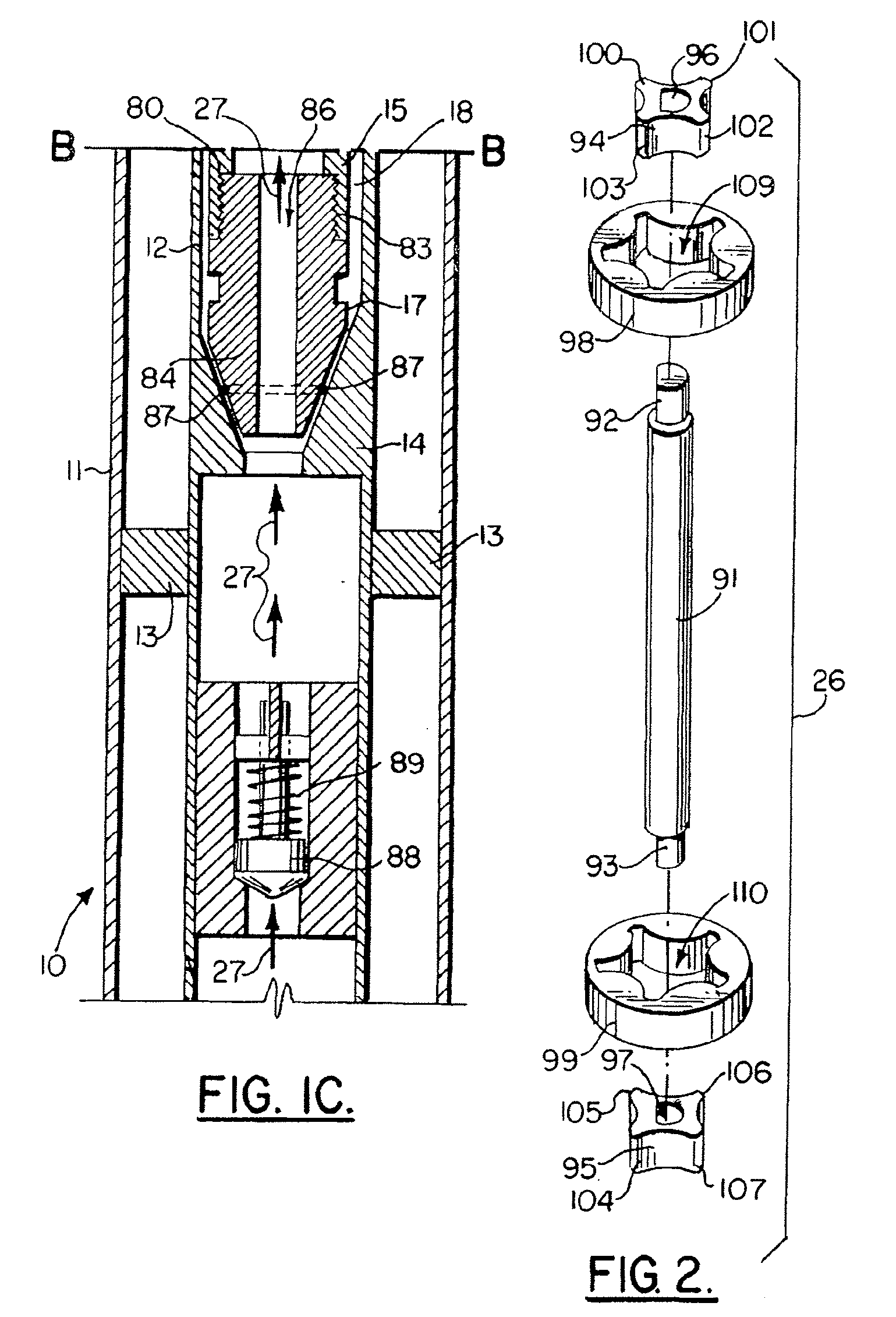
[0035]Oil well pump apparatus 10 as shown in the sectional elevation view of FIGS. 1A, 1B and 1C are in the lines A-A in FIGS. 1A and 1B are match lines and the lines B-B in FIGS. 1B and 1C are match lines. Oil well pump 10 is to be used in a well casing 11 that surrounds production tubing 12. A packer 13 is set in between casing 11 and production tubing 12 as shown in FIG. 1C. Landing nipple 14 is positioned above packer 13. The landing nipple 14 receives the lower end portion 17 of tool body 15 as shown in FIG. 1C. Tool body 15 can be pumped hydraulically (FIG. 11A) or lowered into the production tubing 12 bore 18 using a work string (not shown) that grips neck portion 32 at tool body 15 upper end 16.

[0036]The apparatus 10 of the present invention provides an oil well pump 10 that has a tool body 15 that is elongated to fit inside of the bore 18 of production tubing 12 as shown in FIGS. 1A-1C. A well annulus 19 is that space in between casing 11 and production tubing 12. During us...


PUM


Abstract

An oil well pumping apparatus for pumping oil from a well to a wellhead provides a tool body that is sized and shaped to be lowered into the production tubing string of the oil well. A working fluid is provided that can be pumped into the production tubing. A prime mover is provided for pumping the working fluid. A flow channel into the well bore enables the working fluid to be circulated from the prime mover via the production tubing to the tool body at a location in the well and then back to the wellhead area. A pumping mechanism is provided on the tool body, the pumping mechanism including upper and lower spur gear or gears. The upper spur gear is driven by the working fluid. The lower spur gear is rotated by the first spur gear. The upper and lower spur gears are connected with a common shaft. If upper pairs and lower pairs of spur gears are employed, each upper and lower gear are connected via a common shaft. The tool body has flow conveying portions that mix the working fluid and the produced oil as the oil is pumped. The pumping mechanism transmits the commingled fluid of oil and working fluid to the wellhead area where they are separated and the working fluid recycled.

Description

CROSS-REFERENCE TO RELATED APPLICATIONS[0001]This is a continuation in part of U.S. Ser. No. 10 / 372,533, filed Feb. 21, 2003, now U.S. Pat. No. 7,275,592.STATEMENT REGARDING FEDERALLY SPONSORED RESEARCH OR DEVELOPMENT[0002]Not applicableREFERENCE TO A “MICROFICHE APPENDIX”[0003]Not applicableBACKGROUND OF THE INVENTION[0004]1. Field of the Invention[0005]The present invention relates to oil well pumps. More particularly, the present invention relates to a downhole oil well pump apparatus that uses a circulating working fluid to drive a specially configured pump that is operated by the working fluid and wherein the pump transmits oil from the well to the surface by commingling the pumped oil with the working fluid, oil and the working fluid being separated at the wellhead or earth's surface. Even more particularly, the present invention relates to an oil well pump that is operated in a downhole cased, production pipe environment that utilizes a pump having a single pump shaft that ha...

Claims


Application Information

Patent Timeline
IPC IPC(8): F04F3/00
CPCE21B43/129F01C13/04F04C2/102F04C2/12F04C11/003F04C2240/806F04C2210/10F04C2210/12F04C2210/24F04C2240/30F04C13/008F04C2/10
Inventor DAVIS, RAYMOND C.
Owner DAVIS RAYMOND C
Why Eureka
Try Eureka