Method and Device for Low Delay Processing

a low delay and processing method technology, applied in the field of signal processing, can solve the problems of group delay in the process, reduced control and integrity of delay differences, and perception coherence, so as to reduce the rate of gain variation and reduce such errors

Active Publication Date: 2009-01-15
CIRRUS LOGIC INT SEMICON
View PDF12 Cites 25 Cited by
  • Summary
  • Abstract
  • Description
  • Claims
  • Application Information

AI Technical Summary

Benefits of technology

[0056]Embodiments of the invention may apply preventative measures to reduce the rate of gain variation between the desired gains, such that the synthesised filter is more likely to be able to replicate the desired response. For example, a difference between desired gains in adjacent transform domain sub

Problems solved by technology

A design problem in many signal processing applications is to perform a given task or algorithm on a signal while introducing as little delay as possible.
Specific problems can include:increased perceivable echo from network or acoustic sources;reduced perceptual coherence between user's own voice and side-tone or assisted listening path;reduced perceptual coherence between listening cues & other sensory (eg visual) cues;reduced control and integrity of delay differences in binaural listening;reduced opportunity to avoid other perceptual problems, such as the occlusion e

Method used


Image

  • Method and Device for Low Delay Processing
  • Method and Device for Low Delay Processing
  • Method and Device for Low Delay Processing

Examples


first embodiment

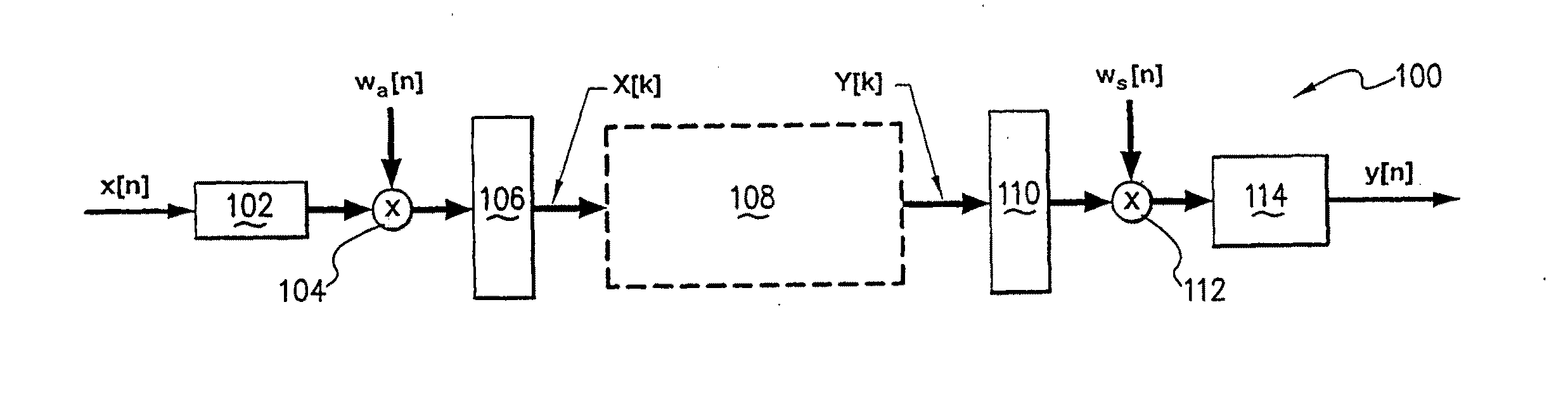
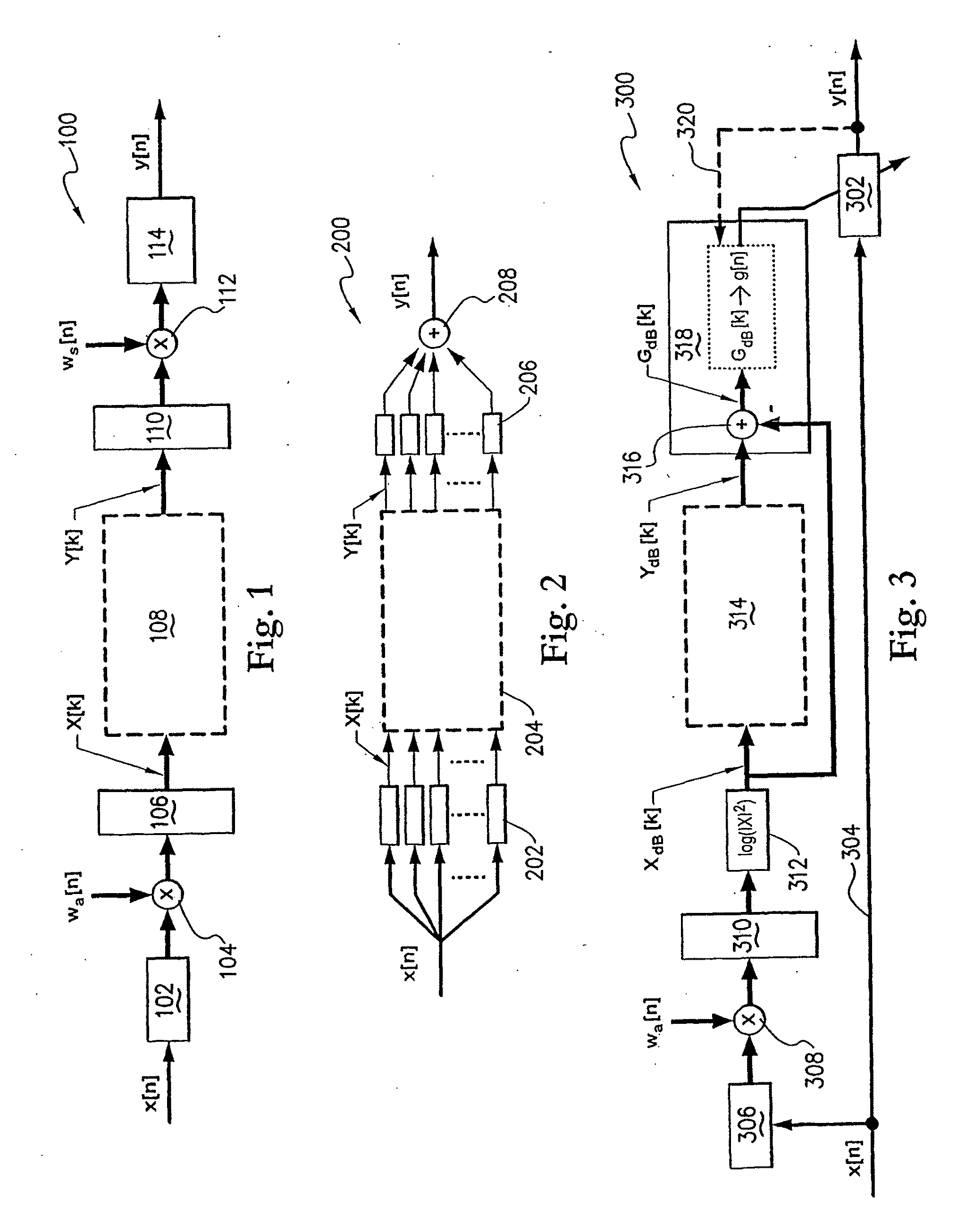
[0111]the invention set out in FIG. 3 recognises that the delay in the block based FFT mechanism 306, 310, 314, etc, is a requirement for the analysis of the signal x[n] only. Thus, the structure 300 of FIG. 3 provides for multi-band processing with reduced group delay using a computationally efficient FFT scheme by ‘de-coupling’ the signal analysis path from the processing path 304. This is achieved by using an offline analysis scheme that uses block processing for the analysis path, but adapts one or more time domain filters 302 to perform the processing of the signal x[n] at a single sample rate or reduced block size rate.

[0112]The circuit 300 of FIG. 3 performs multi-band analysis and processing based on log power domain (eg dB level) FFT analyses of the input signal, by provision of block 312. This is particularly convenient for many audio conditioning algorithms such as dynamic range compression or ADRO. Nevertheless alternate embodiments may omit block 312 and forgo log power...

fourth embodiment

[0140]FIG. 8 illustrates a filter realisation block 800 in accordance with the invention, using the cepstral minimum phase approximation technique for filter realization in the type of structure depicted in FIG. 3. An important advantage in combining the structures of FIGS. 3 & 8 is that block 312 provides for the core processing to be performed in the log domain (dB or other basis) prior to gain calculation and filter realization. This is particularly convenient for cepstrum calculations which require the input to be in the log domain. Therefore, in the flow of FIG. 3, the filter gain specification given by the real logarithmic gain values GdB[k] can be input directly to IFFT 804 for initial calculation of the real cepstrum c[q] in the flow of the filter design process of FIG. 8.

[0141]Once the real cepstrum c[q] of the log gain specification is calculated (c[q]=IFFT(GdB[k])), it is element-wise multiplied at 806 by a folding sequence λmin[q] to produce a modified cepstrum ĉmin[q]=λ...

fifth embodiment

[0148]While these or other windows may in some embodiments of the invention prove suitable for appropriate applications, an alternate cepstral implementation of filter realisation has been recognised by the present invention. Rather than attempt to choose or synthesize an asymmetric time domain window ws[n], spectral smoothing of the filter specification is obtained by recognising and exploiting another property of the cepstrum, referred to as cepstral smoothing, cepstral homomorphic filtering or ‘liftering’. The goal of such smoothing is to apply a low-pass or single sided function to weight the ends of the cepstrum. Since the ‘high exponential’ or ‘high quefrency’ components of the cepstrum generally represent the faster variations in the spectral domain, the spectrum can be smoothed if these components are weighted down relative to the ‘low exponential’ or ‘low quefrency’ components.

[0149]Cepstral filtering is therefore ideal for smoothing the minimum phase spectrum prior to trun...


PUM


Abstract

Adaptively processing an input signal, such as an input signal of a hearing aid. The input signal is passed through an adaptive time domain filter to produce an output signal. At least one of the input signal and the output signal is used as an analysis signal. The analysis signal is transformed into a transform domain to produce a transformed analysis signal, which is analysed to produce a desired gain for each respective transform domain sub-band. A minimum phase time domain filter characteristic is synthesised which approaches the desired gains. The adaptive filter is updated with the synthesised filter characteristic.

Description

CROSS-REFERENCE TO RELATED APPLICATIONS[0001]The present application claims priority from Australian Provisional Patent Application No 2006900854 filed on 21 Feb. 2006, the content of which is incorporated herein by reference.FIELD OF THE INVENTION[0002]The present invention relates to signal processing, and in particular relates to adaptively processing a signal in a manner which introduces minimal delay.BACKGROUND TO THE INVENTION[0003]A design problem in many signal processing applications is to perform a given task or algorithm on a signal while introducing as little delay as possible. This delay is usually characterized by a measure known as group delay, defined as the negative rate of change of the total introduced phase shift with respect to angular frequency, −dθ / dω. A filter or system that introduces a constant group delay with respect to frequency is said to have linear phase. A filter or system with non-linear phase introduces variable delay with frequency (A. V. Oppenhei...

Claims


Application Information

Patent Timeline
IPC IPC(8): H04B1/10G10L21/0324G10L25/24
CPCH03H21/0012H03H21/0016G10L21/0364H04R25/505H04R2225/43H03H17/0216H03H17/0294H03H17/0211
Inventor DICKSON, BONARSTEELE, BRENTON ROBERT
Owner CIRRUS LOGIC INT SEMICON
Why Eureka
Try Eureka