
Apparatus and method for processing pulse waves

Active Publication Date: 2009-01-15
TDK CORPARATION
View PDF5 Cites 122 Cited by
  • Summary
  • Abstract
  • Description
  • Claims
  • Application Information

AI Technical Summary

Benefits of technology

[0008]According to one aspect of the present invention, a pulse wave processing apparatus includes an obtaining unit that obtains pulse wave signal data expressing a pulse wave of a subject and body movement signal data expressing body movements of the subject; a correlation coefficient calculating unit that calculates a correlation coefficient expressing a degree of correlation between the pulse wave signal data and the body movement signal data; and a pulse wave eliminating unit that eliminates one or more pieces of the pulse wave signal data in which the correlation coefficient is equal to or larger than a predetermined threshold value.
[0009]According to another aspect of the present invention, a pulse wave processing method executed b

Problems solved by technology

The subject is greatly burdened if he / she needs to have the electrodes attached to his / her body all the time while he / she leads his / her daily life.
However, a problem arises where, when pulse waves are measured, the waveforms are more greatly influenced and disturbed by movements of the body (hereinafter “body movements”) than when electrocardiography is used.
These techniques are suitable for the use during physical exercises; however, in the case where the body movement signal and the pulse wave signal are in substantially the same frequency bandwidth, a problem remains where it is difficult to eliminate the body movement components.
Also, it is not possible to use these techniques for the purpose of extracting the interval for each pulse beat of the pulse wave and performing an autonomic nerve analysis based on an analysis of the frequency of the fluctuation component.
According to this method, it is possible to judge whether each of the parts of the pulse wave should be used or not in correspondence with each pulse beat; however, in the case where a body movement that exceeds a predetermined magnitude is made, there is a possibility that all of the parts of the pulse wave may be judged to be unusable, and even some parts of the data that properly express the measured pulse wave may be lost.

Method used


Image

  • Apparatus and method for processing pulse waves
  • Apparatus and method for processing pulse waves
  • Apparatus and method for processing pulse waves

Examples


Embodiment Construction

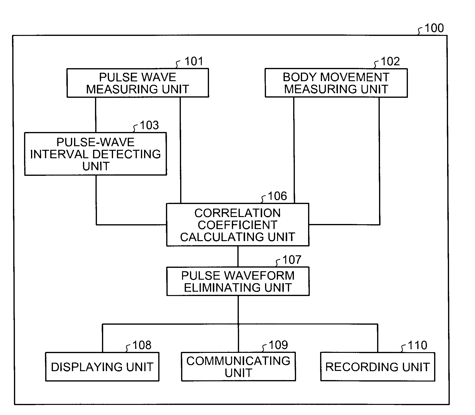
[0028]FIG. 1 is a block diagram of a pulse wave processing apparatus 100 according to an exemplary embodiment of the present invention. As shown in FIG. 1, the pulse wave processing apparatus 100 includes a pulse wave measuring unit 101, a body movement measuring unit 102, a pulse-wave interval detecting unit 103, a correlation coefficient calculating unit 106, a pulse waveform eliminating unit 107, a displaying unit 108, a communicating unit 109, and a recording unit 110.

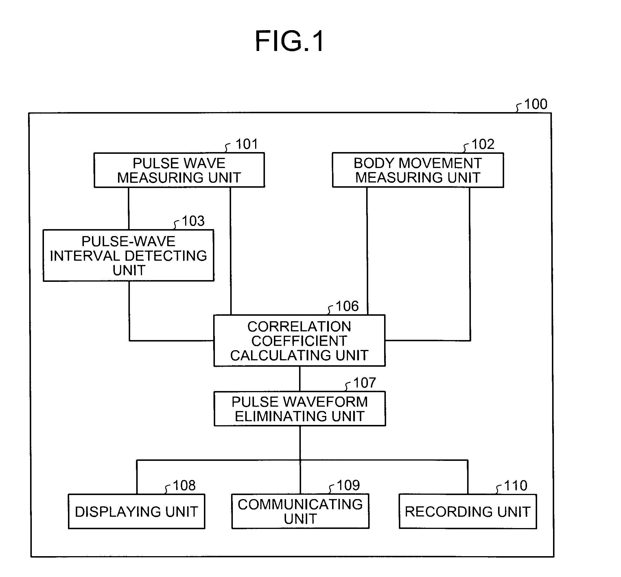
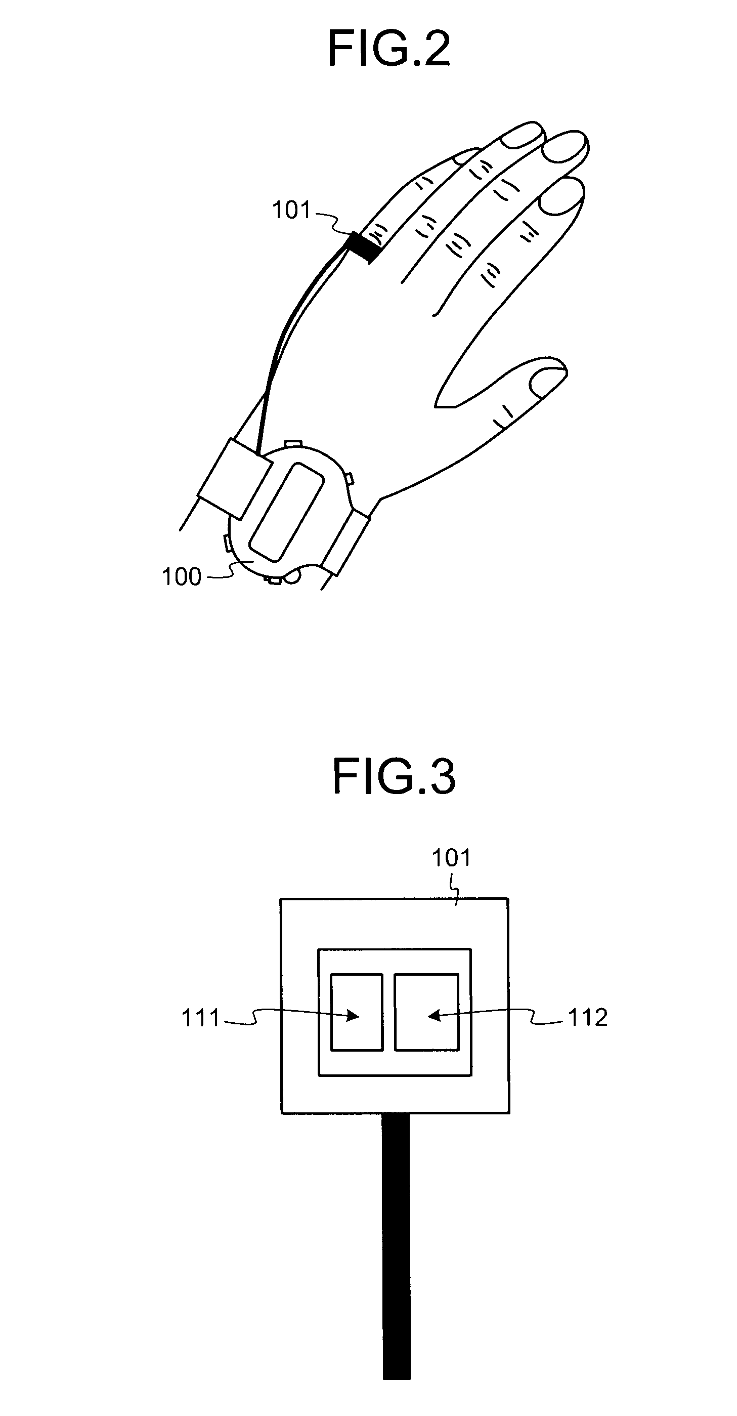
[0029]FIG. 2 is a drawing illustrating an example of the exterior appearance of the pulse wave processing apparatus 100 and how it is attached to a subject. In this example, the pulse wave processing apparatus 100 is worn around a wrist like a wrist watch. The pulse wave measuring unit 101 is wound around a finger so that the pulse wave is measured at the finger abdomen.

[0030]FIG. 3 is a schematic drawing illustrating the pulse wave measuring unit 101. The pulse wave measuring unit 101 includes a photoelectric puls...


PUM


Abstract

Pulse wave signal data expressing the pulse wave of a subject and body movement signal data expressing body movements of the subject are obtained so that a correlation coefficient expressing the degree of correlation between the pulse wave signal data and the body movement signal data is calculated. One or more pieces of the pulse wave signal data in which the correlation coefficient is equal to or larger than a predetermined threshold value are eliminated.

Description

CROSS-REFERENCE TO RELATED APPLICATIONS[0001]This application is based upon and claims the benefit of priority from the prior Japanese Patent Application No. 2007-177173, filed on Jul. 5, 2007; the entire contents of which are incorporated herein by reference.BACKGROUND OF THE INVENTION[0002]1. Field of the Invention[0003]The present invention relates to a pulse wave processing apparatus and a pulse wave processing method for processing pulse wave signals as data.[0004]2. Description of the Related Art[0005]An example of biomarkers that prominently reflect the state of a subject is heartbeats (e.g., autonomic nerve activities based on analysis of heartbeat rates and frequencies of heartbeat intervals). Electrocardiography is commonly used to measure heartbeats directly. To perform electrocardiography, it is necessary to paste electrodes on the subject in, for example, a number of places on the chest. The subject is greatly burdened if he / she needs to have the electrodes attached to ...

Claims


Application Information

Patent Timeline
IPC IPC(8): A61B5/02
CPCA61B5/0002A61B5/02A61B2562/0219A61B5/6816A61B5/721A61B5/681
Inventor OUCHI, KAZUSHIGESUZUKI, TAKUJI
Owner TDK CORPARATION
Learn More