Supercharge Your Innovation With Domain-Expert AI Agents!

Encoder apparatus and calibration method of the same apparatus

a technology of encoder apparatus and calibration method, which is applied in the direction of optical conversion of sensor output, speed measurement using gyroscopic effects, instruments, etc., can solve the problems of different increase of digital signal and inability to uniformly produce sinusoidal wave output for a certain time period

Inactive Publication Date: 2009-01-15
S PRINTING SOLUTION CO LTD
View PDF15 Cites 2 Cited by
  • Summary
  • Abstract
  • Description
  • Claims
  • Application Information

AI Technical Summary

Benefits of technology

[0027]The calculating the position of the object may include determining whether respective signs of the output linear functions in a predetermined time period are changed, calculating information related to an increase direction or a decrease direction of an encoder step, and outputting a first position value by adjusting a position according to the calculated information related to the increase direction or the decrease direction of the encoder step.

Problems solved by technology

Meanwhile, because the analogue output of the analogue encoder apparatus is a sinusoidal wave signal, there is a problem of a different increase in the digital signal depending on an output level of the analogue signal.
However, if a sinusoidal wave is output, an output amount of the sinusoidal wave for a certain time period is not uniform.

Method used


Image

  • Encoder apparatus and calibration method of the same apparatus
  • Encoder apparatus and calibration method of the same apparatus
  • Encoder apparatus and calibration method of the same apparatus

Examples


Embodiment Construction

[0048]Reference will now be made in detail to the embodiments of the present general inventive concept, examples of which are illustrated in the accompanying drawings, wherein like reference numerals refer to like elements throughout. The embodiments are described below in order to explain the present general inventive concept by referring to the figures.

[0049]An encoder apparatus according to an embodiment of the present general inventive concept may be used, for example, to precisely measure an object position in an image forming apparatus by measuring a rotated amount of a feeding roller of the image forming apparatus with an input analogue signal.

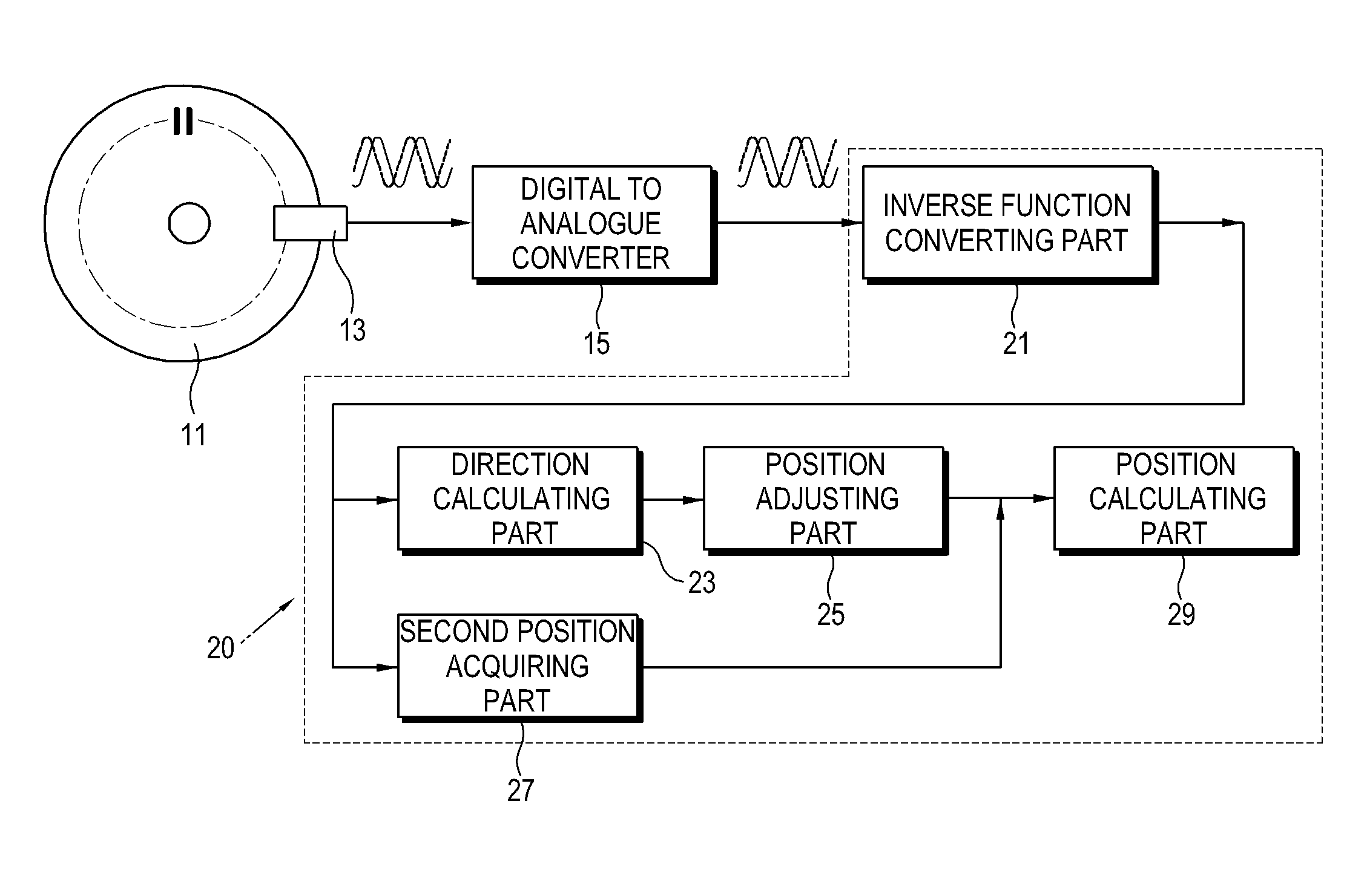
[0050]Referring to FIG. 3, an encoder apparatus in accordance with an embodiment of the present general inventive concept may include a driving plate 11 to vary with the position of the object, an optical device 13 to output a sinusoidal wave analogue signal which varies according to the movement of the driving plate 11, an analogue to ...


PUM


Abstract

An encoder apparatus to measure a position of an object from an input analogue signal includes a driving plate which varies according to the position of the object, an optical device to receive a light response from the driving plate and to output a sinusoidal wave analogue signal according to an amount of the driving plate's movement, an analogue to digital (A / D) converter to output a normalized sinusoidal wave digital signal converted from the analogue signal outputted from the optical device, and a calibration unit to convert the sinusoidal wave digital signal outputted from the A / D converter into a triangular wave signal.

Description

CROSS-REFERENCE TO RELATED APPLICATIONS[0001]This application claims priority under 35 U.S.C. §119(a) from Korean Patent Application No. 10-2007-0070597, filed on Jul. 13, 2007 in the Korean Intellectual Property Office, the disclosure of which is hereby incorporated herein in its entirety by reference.BACKGROUND OF THE INVENTION[0002]1. Field of the Invention[0003]The present general inventive concept relates to an encoder apparatus and a calibration method of the same apparatus, and more particularly, to an encoder apparatus and a calibration method of the encoder apparatus to sense and measure a microscopic movement of an object by converting a sinusoidal wave signal output from an optical device to a triangular wave signal.[0004]2. Description of the Related Art[0005]An apparatus requiring a precise control generally adopts a two channel analogue encoder for a precise transfer of an object to be moved.[0006]For example, an image forming apparatus like an inkjet printer typically...

Claims


Application Information

Patent Timeline
Patent Type & Authority Applications(United States)
IPC IPC(8): G06F15/00G01B11/14
CPCG01D5/24452G01D5/347G01D5/2448G01D18/001G01D5/26G01D18/00
Inventor YL, KYOUNG-MOK
Owner S PRINTING SOLUTION CO LTD
Features
  • R&D
  • Intellectual Property
  • Life Sciences
  • Materials
  • Tech Scout
  • Unparalleled Data Quality
  • Higher Quality Content
  • 60% Fewer Hallucinations
Learn More