
Spray hole profile

Active Publication Date: 2009-01-22
DELPHI TECH IP LTD
View PDF8 Cites 22 Cited by
  • Summary
  • Abstract
  • Description
  • Claims
  • Application Information

AI Technical Summary

Benefits of technology

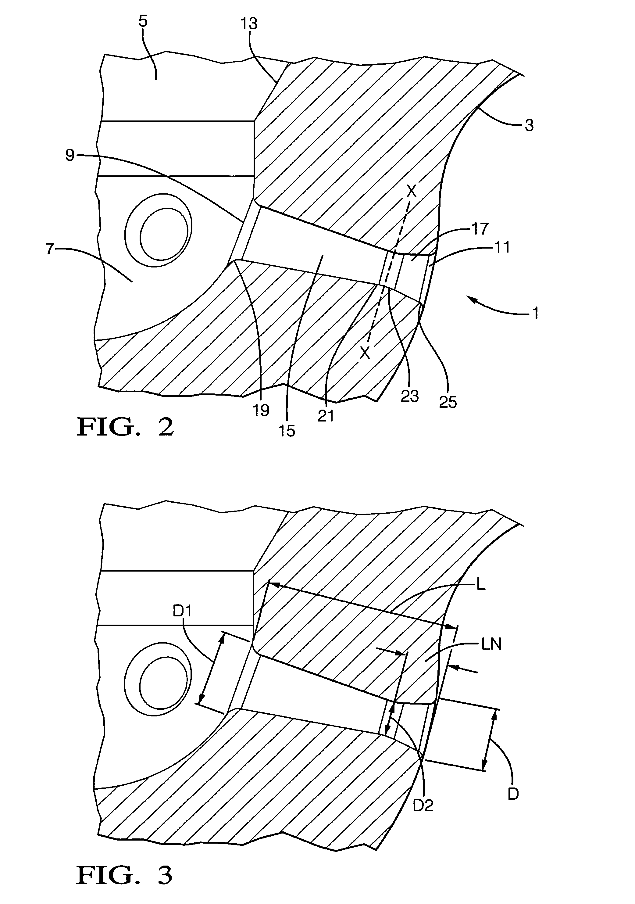
[0003]Accordingly, the present invention provides a fuel injector for an internal combustion engine comprising a nozzle body having at least one spray hole, wherein the at least one spray hole has a hole entry on the inside of the nozzle body and a hole exit on the outside of the nozzle body and the spray hole is provided with a hole entry section which, starting from the hole entry, has a flow area which decreases from a relatively larger flow area at the hole entry to a relatively small flow area at the intersection between the end of the hole entry section and the start of a hole exit section, wherein the hole exit section, starting from the intersection with the hole entry section, has a flow area which increases from a relatively small flow area at the intersection with the hole entry section to a relatively larger flow area at the hole exit. The described spray hole profile improves the fuel flow characteristics through the spray hole and thus improves the efficiency of the nozzle.
[0008]Preferably, the hole entry and the hole exit are provided with a radius. The provision of a radius improves the flow characteristics of fuel passing through the spray hole.
[0009]Preferably, the intersection between the hole entry section and the hole exit section is provided with a radius. The provision of a radius removes the sharp edge that would otherwise exist at the intersection and hence improves the flow characteristics of fuel passing through the spray hole.

Problems solved by technology

It has been discovered that tapered spray holes which have a diametrical cross-section that reduces in size from the inside surface of the nozzle body to the outside surface of the nozzle body, such as that described in EP 0 352 926, are prone to the formation of deposits within the hole which reduce its diameter and change its flow characteristics.
The main problem with the formation of deposits is that the maximum flow rate through the spray hole is reduced and this is detrimental to the performance of the engine into which the injector is installed.

Method used


Image

  • Spray hole profile
  • Spray hole profile
  • Spray hole profile

Examples


Embodiment Construction

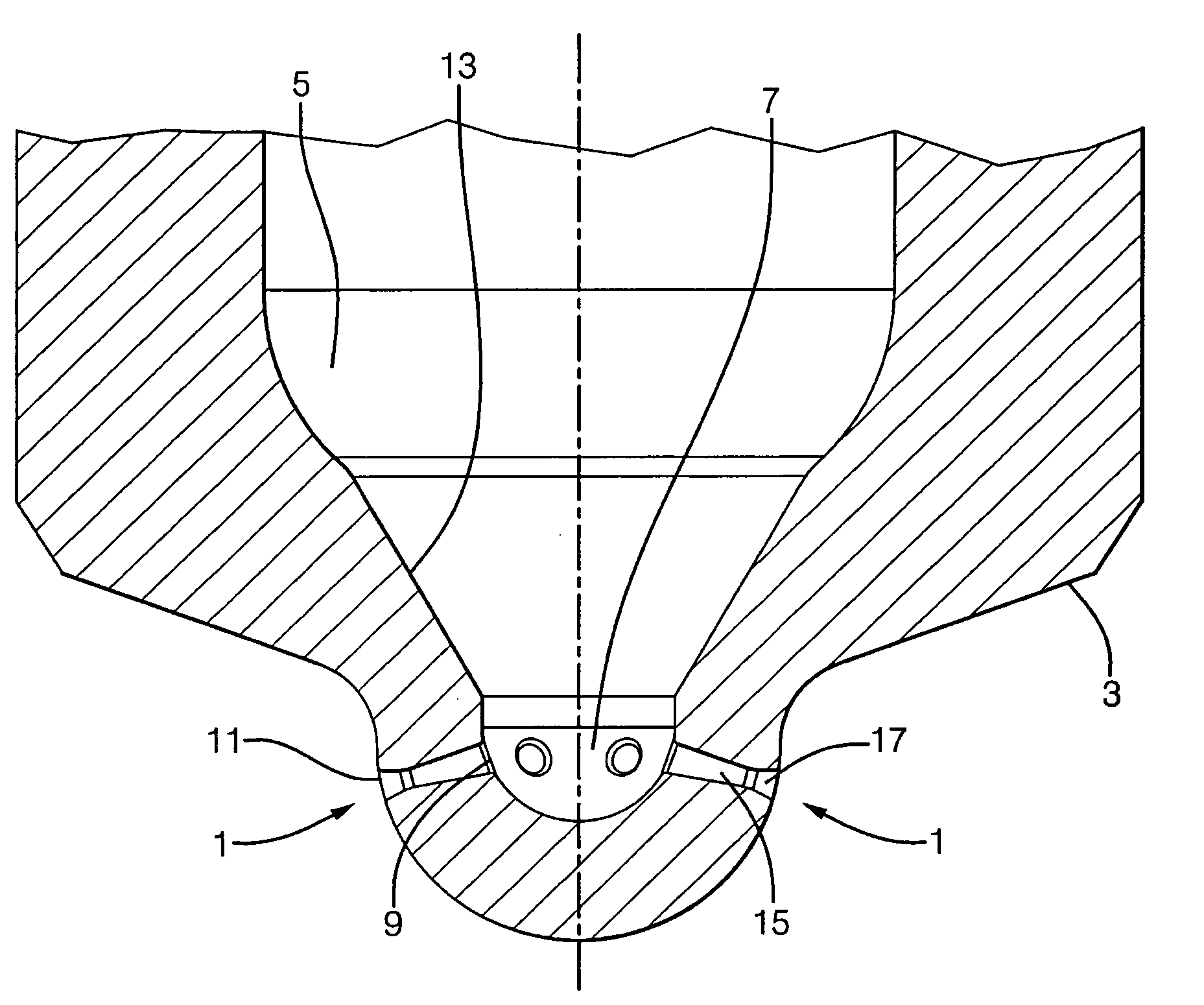
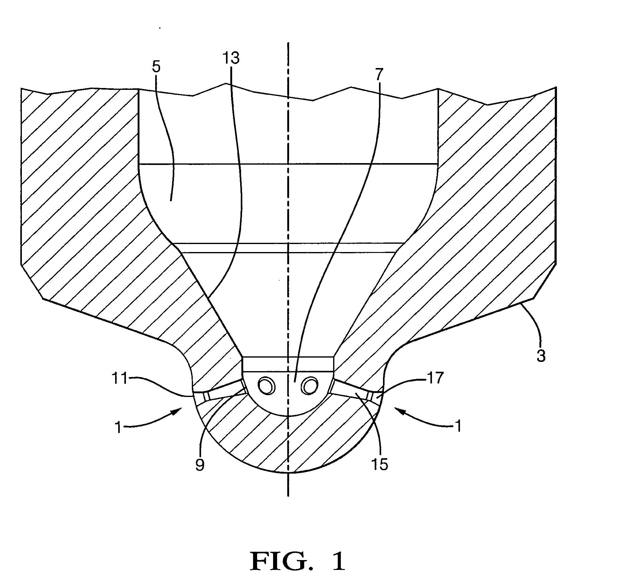
[0019]FIG. 1 is a cross-sectional view of the tip portion of a fuel injector nozzle having six spray holes 1 according to the present invention (four of which are shown). The tip portion comprises a hollow generally cylindrical nozzle body 3 which defines an internal fuel delivery chamber 5 which terminates at the tip portion of the injector in a sac 7. Each spray hole 1 has a hole entry 9 located in the sac 7 and a hole exit 11 located on the external surface of the nozzle body 3, so that fuel contained with the delivery chamber 5 can be injected out of the nozzle. In order to control injection of the fuel a valve needle (not shown) is provided which is axially moveable within the chamber 5 and which in a first position seals against a valve seat 13 defined by the walls of the fuel delivery chamber 5, adjacent to the tip portion of the injector nozzle, in order to prevent fuel injection, and which is moveable away from the valve seat 13 in order to initiate fuel injection through t...


PUM

PropertyMeasurementUnit
Fractionaaaaaaaaaa
Fractionaaaaaaaaaa
Fractionaaaaaaaaaa

Abstract

A fuel injector for an internal combustion engine comprising a nozzle body having at least one spray hole. The at least one spray hole has a hole entry on the inside of the nozzle body and a hole exit on the outside of the nozzle body. The spray hole is provided with a hole entry section which, starting from the hole entry, has a flow area which decreases from a relatively larger flow area at the hole entry to a relatively small flow area at the intersection between the end of the hole entry section and the start of a hole exit section. The hole exit section, starting from the intersection with the hole entry section, has a flow area which increases from a relatively small flow area at the intersection with the hole entry section to a relatively larger flow area at the hole exit.

Description

TECHNICAL FIELD[0001]The present invention relates to a spray hole profile for use in a fuel injector for an internal combustion engine. In particular, the present invention relates to a spray hole having convergent and divergent sections.BACKGROUND OF THE INVENTION[0002]It has been discovered that tapered spray holes which have a diametrical cross-section that reduces in size from the inside surface of the nozzle body to the outside surface of the nozzle body, such as that described in EP 0 352 926, are prone to the formation of deposits within the hole which reduce its diameter and change its flow characteristics. The main problem with the formation of deposits is that the maximum flow rate through the spray hole is reduced and this is detrimental to the performance of the engine into which the injector is installed. Consequently, it is desired to have an improved design which prevents any reduction in the flow rate.SUMMARY OF THE INVENTION[0003]Accordingly, the present invention ...

Claims


Application Information

Patent Timeline
IPC IPC(8): F02M61/00B23P15/16
CPCY10T29/49432F02M61/1806
Inventor LIMMER, ANDREW J.PIMENTA, RICARDODICK LAMBERT, MALCOLM DAVIDSOTERIOU, CELIA C.
Owner DELPHI TECH IP LTD
Learn More