Check patentability & draft patents in minutes with Patsnap Eureka AI!

Method, system and support mechanism for object identification

Inactive Publication Date: 2009-01-22
PSION
View PDF16 Cites 14 Cited by
  • Summary
  • Abstract
  • Description
  • Claims
  • Application Information

AI Technical Summary

Benefits of technology

[0016]It is an object of the invention to provide a method and system that obviates or mitigates at least one of the disadvantages of existing systems.
[0021]The present invention provides reliable, fast identification of items at specific points as they travel through a system, by combining manual and automatic identification technologies.

Problems solved by technology

All of the above means of identification have problems associated with their use.
Although extremely fast, RFID is not a completely reliable means of identification.
RFID may fail due to the sensitive nature of electromagnetic radiation at radio frequencies to interference, reflection and absorption of the radio waves.
Manual identification of any means including barcode reading is undesirable because of the need for a human operator.
Human visual identification is even more undesirable because of the time it takes for a human to feed the information into an electronic system, and because of the possibility of human error.
A system employing Automatic identification, such as RFID, can allow for a very high throughput of objects through the system, but to sustain this high throughput, some quality of identification must be compromised due to the inherent problems with this identification method.
If the objects in the system have a high value associated with them, letting the quality of identification fall to maintain the throughput is undesirable, the value added by moving objects through the system quickly may be lost if there are any opportunities for high value items to get lost or stolen.
Only the largest corporations can mandate that the external suppliers into the system attach an RFID tag to an object before it enters the system, and applying RFID tags to all objects is currently not economically viable, because the RFID tag's value could be high compared to the object it is applied to.
This handheld computer is a separate entity from the primary means of Automatic identification, and as such has its own capital cost, and cost of ownership associated, on top of the cost of the primary, and unreliable Automatic identification system.
If the business process is changed, requiring Automatic identification to occur in a different location, moving the Automatic identification system to a new location is a time consuming and expensive undertaking.

Method used


Image

  • Method, system and support mechanism for object identification
  • Method, system and support mechanism for object identification
  • Method, system and support mechanism for object identification

Examples


Embodiment Construction

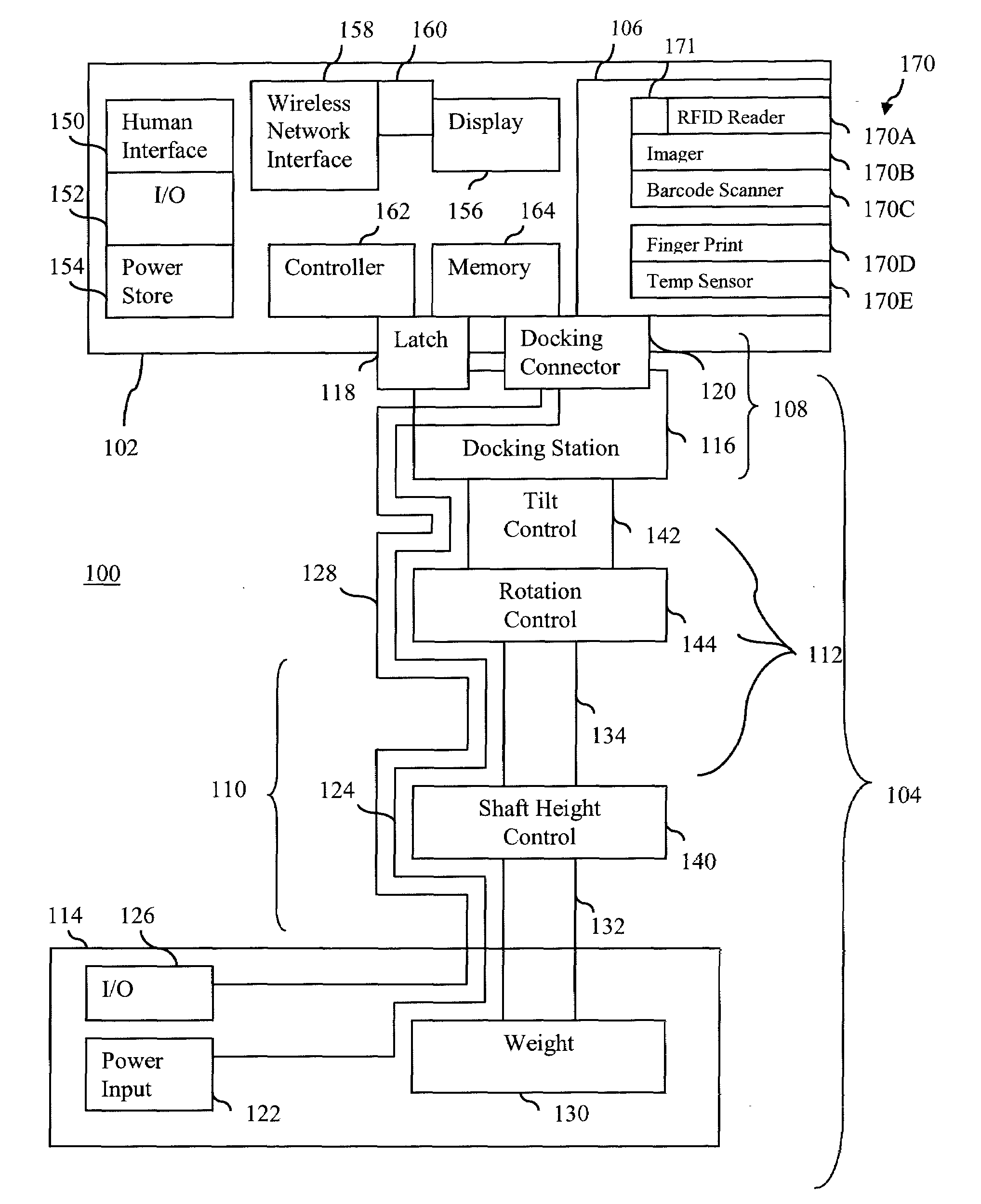
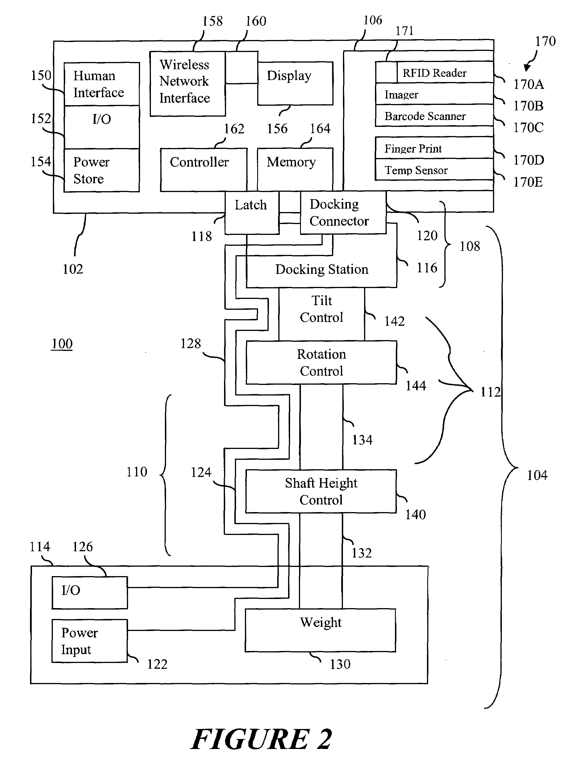
[0035]FIG. 2 illustrates an example of an apparatus for manual and automatic identification in accordance with an embodiment of the present invention. The apparatus 100 of FIG. 1 includes a removable handheld data capture and identification terminal 102 and a fixture 104 for securely supporting the handheld terminal 102. The terminal 102 is removable docked onto the fixture 104. The terminal 102 is operated without intervention of the human operator. The terminal 102 is operable under the guidance of the human operator without the fixture 104 (stand alone) if required.

[0036]In the description, the terms “(removable) handheld data capture and identification terminal 102” and “(handheld) terminal 102” are used interchangeably. In the description, the terms “connect (connected)”, “couple (coupled)”, “engage (engaged)” may be used interchangeably, and these terms may indicate that two or more elements are in physical or electrical contact with each other. In the description, the terms “...


PUM


Abstract

A method, system and support mechanism for object identification is provided. A removable handheld terminal is operable as a stand-alone device. A fixture is connectable to the handheld terminal for a portal use. The terminal includes one or more sensors being automatically or manually activated. The fixture includes a docking member for removably connecting the handheld terminal to the fixture.

Description

FIELD OF INVENTION[0001]The present invention relates to signal processing technology and more particularly to a method, system and support mechanism for object identification.BACKGROUND OF THE INVENTION[0002]Identification of objects and digitization of the identification data allows for control of the flow of said objects through a distribution system, and improves the visibility of objects in the system, to the software controlling the system itself and to remote human observers of the system.[0003]Digitization of the location and identity of objects in the system allows for automatic routing of objects in the system to their correct destination via logical software control. It also allows for improved efficiency of the overall system by allowing the present location of an object to be known, and therefore it's likely time of arrival to be better estimated.[0004]Automatic identification is a process which allows the identity of objects to be determined without human intervention....

Claims


Application Information

Patent Timeline
IPC IPC(8): G08B13/14
CPCG06K7/109G06K7/10881
Inventor STAGG, ADRIAN JOSEPH
Owner PSION
Features
  • R&D
  • Intellectual Property
  • Life Sciences
  • Materials
  • Tech Scout
  • Unparalleled Data Quality
  • Higher Quality Content
  • 60% Fewer Hallucinations
Learn More