Method of Customizing 3D Computer-Generated Scenes

a computer-generated scene and customization technology, applied in the field of 3d computer-generated scene customization, can solve the problems of affecting the ambient occlusion of the scene, material or texture changes may need to be reflected or refracted, etc., and achieve the effect of low cost, high cost and high quality

Inactive Publication Date: 2009-01-22
PIXBLITZ STUDIOS
View PDF4 Cites 124 Cited by
  • Summary
  • Abstract
  • Description
  • Claims
  • Application Information

AI Technical Summary

Benefits of technology

[0025]The present invention discloses an automated method of rapidly producing customized 3D graphics images that appear to have been created by a costly 3D graphics production and rendering process, but which in fact have been automatically created by a much lower cost process optimized to render only the changed parts of the 3D scene, and the effect of the changed parts on the rest of the scene. For example, a changed material or texture may need to get reflected or refracted, possibly recursively, and affecting the ambient occlusion of the scenes and hence the image. Here a master 3D graphics model is produced one-time by an “expensive” 3D graphics model and a special diagnostic rendering process. This expensive master 3D graphics scene can then be rapidly and automatically blended or merger or 3D composited with any number of custom 3D scenes, objects, graphic images, and movies by an optimized rendering process in a way that preserves important rendering details, resulting in a final 3D image that looks as if it had been processed from the beginning by a computationally intensive rendering process.
[0026]The invention allows the high cost of an original 3D graphics model and diagnostic rendering process to be amortized by the many different customized variants, producing many different high quality but customized 3D images and movies that can be used for a variety of different purposes and users.

Problems solved by technology

For example, a changed material or texture may need to get reflected or refracted, possibly recursively, and affecting the ambient occlusion of the scenes and hence the image.

Method used


Image

  • Method of Customizing 3D Computer-Generated Scenes
  • Method of Customizing 3D Computer-Generated Scenes
  • Method of Customizing 3D Computer-Generated Scenes

Examples


Embodiment Construction

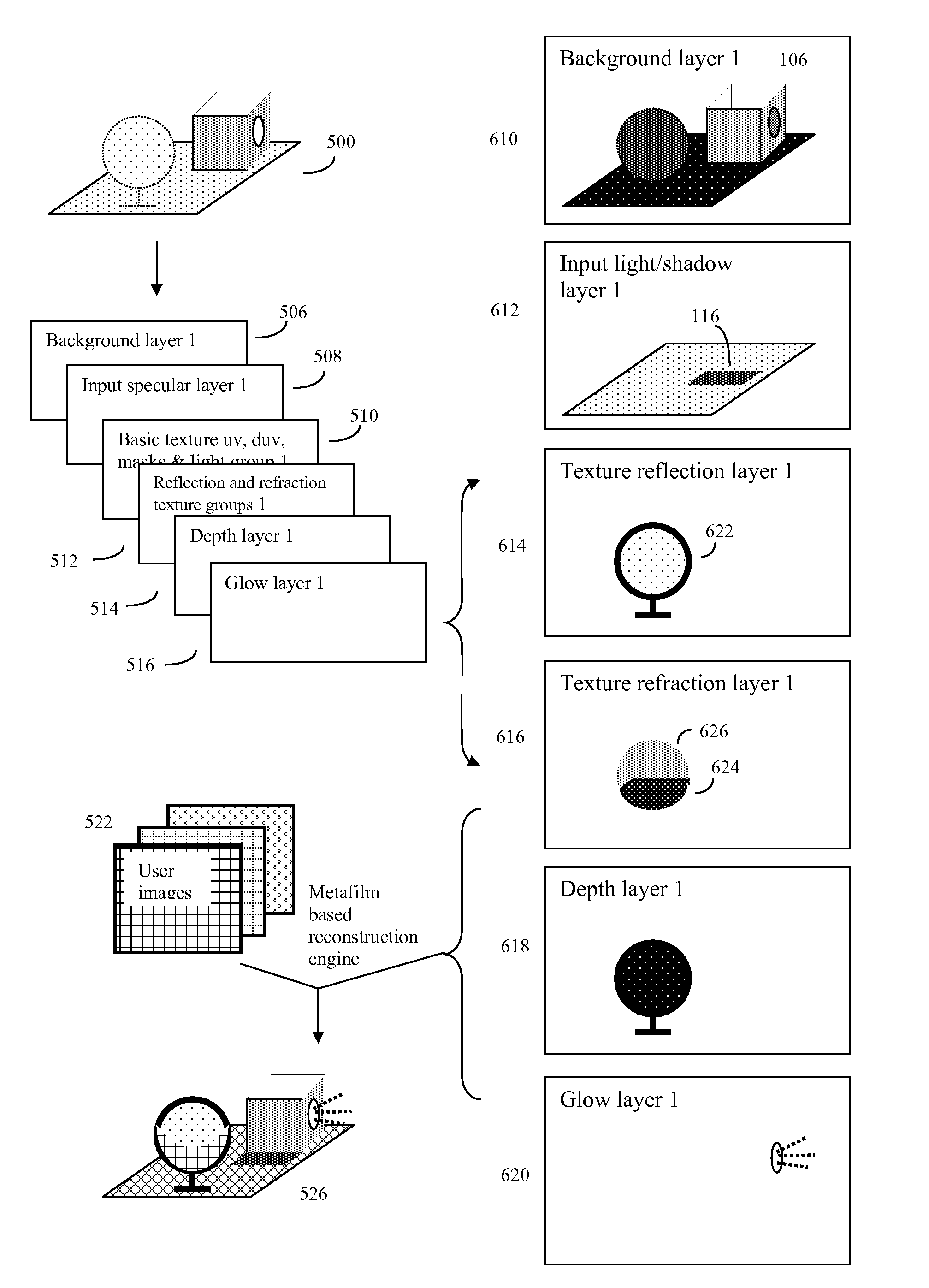
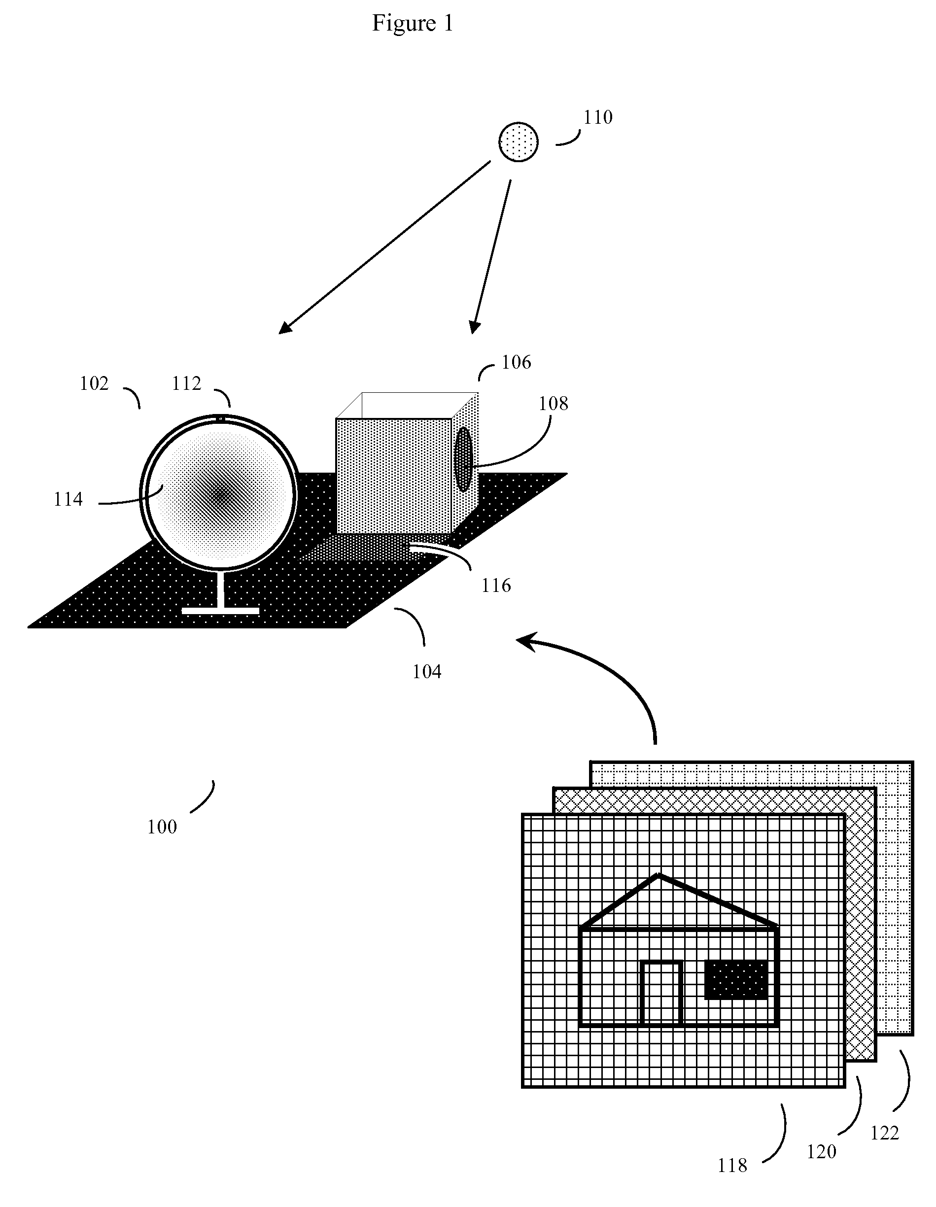
[0035]To better understand the nature of the problem, consider what happens in a situation where a 3D graphics model is rendered and viewed from a moving point of view, such as in a video. When 3D graphics scenes move, the angles of lighting continually change, various 3D objects are blocked and unblocked by other 3D objects, images from one 3D graphics object, such as a shiny or transparent object, may be refracted or reflected by other 3D graphics objects. Now imagine the problems of simply trying to drop in a new image or video into the rendered scene by a standard digital compositing process, such as alpha blending. Unless the new image or video is processed to look entirely natural in its new context, with variable angles, lighting, surface shapes, surface textures, reflection, refraction etc., the new image or video will look unnatural. Instead of appearing as a real element of the 3D “world”, the new image or video will appear as if it has simply been pasted on to the scene, ...


PUM


Abstract

An automated method of rapidly producing customized 3D graphics images in which various user images and video are merged into 3D computer graphics scenes, producing hybrid images that appear to have been created by a computationally intensive 3D rendering process, but which in fact have been created by a much less computationally intensive series of 2D image operations. To do this, a 3D graphics computer model is rendered into a 3D graphics image using a customized renderer designed to automatically report on some of the renderer's intermediate rendering operations, and store this intermediate data in the form of metafilm. User images and video may then be automatically combined with the metafilm, producing a 3D rendered quality final image with orders of magnitude fewer computing operations. The process can be used to inexpensively introduce user content into sophisticated images and videos suitable for many internet, advertising, cell phone, and other applications.

Description

[0001]This application claims the priority benefit of provisional patent application 61 / 038,946 “Method of Customizing 3D Computer-Generated Scenes”, filed Mar. 24, 2008. The contents of this application are included herein by reference.BACKGROUND[0002]High quality Three Dimensional Computer Generated Imagery (3D-CGI) of real imaginary scenes and landscapes is now ubiquitous. On video games, television, and movies, as well as many different forms of graphic images in print media and web pages, everyone has become quite accustomed to such images, and even realistic images and movies of quite impossible scenes have become so commonplace as to not attract much notice.[0003]Typically 3D-CGI is constructed by a process in which a 3D graphics artist (or a computer program) first creates a computer model of a scene, often by creating multiple different figures or “objects” in wireframe form with multiple vertices and surfaces. The 3D graphics artist will in turn specify the properties of t...

Claims


Application Information

Patent Timeline
Patent Type & Authority Applications(United States)
IPC IPC(8): G06T15/00G06T15/50
CPCG06T15/503G06T15/005
Inventor JOSHI, VIKRAMNYO, DAVID TINKUMAR, POOJAN
Owner PIXBLITZ STUDIOS
Why Eureka
Try Eureka