Determining and correcting for imaging device motion during an exposure

a technology of imaging device and motion, applied in the field of digital signal processing methods, can solve the problems of reducing image sharpness, amplifying noise as well as signal content, and current digital cameras suffering from poor low-light performan

Active Publication Date: 2009-01-22
OMNIVISION TECH INC
View PDF65 Cites 152 Cited by
  • Summary
  • Abstract
  • Description
  • Claims
  • Application Information

AI Technical Summary

Benefits of technology

[0012]According to an embodiment of the present invention, multiple sets of image element acquisition devices, such as CCDs known in the art, are defined on an image sensor. Image element acquisition devices are commonly referred to herein as “pixels” or “image pixels” for purposes of clarity. During capture, signals from a first set of image element acquisition devices, such as CCDs, known in the art, are read out one or more times. Signals from a second set of image element acquisition devices also are read out one or more times. Readouts from at least the first set of image element signals are used to determine estimates of the imaging device motion during the exposure period. Readouts from at least some of the second set of image element signals are used to assemble an output image based at least upon the determined motion.
[0013]In some embodiments of the present invention, four sets of image element acquisition devices are defined on an image sensor. During capture, a first set of image element signals are read out one or more times from a first of the four sets of image element acquisition devices. Respectively, second, third, and fourth sets of image element signals are also read out one or more times from the corresponding sets of image element acquisition devices. Readouts from at least the first set of image elements are used to generate estimates of the imaging device motion during the exposure period. Readouts from at least the second, third and fourth sets of image elements are used to assemble the output image.

Problems solved by technology

Current digital cameras suffer from poor performance in low-light situations, when either a flash is not available, or is not beneficial.
Exposure time can be increased to boost the number of photons reaching the sensor, but this solution typically reduces sharpness in the image if there is any motion in the scene or if the camera is not held absolutely steady.
The problem with this technique is that it amplifies noise as well as signal content.
Low-light images typically have low signal-to-noise ratios, and the gain factor required to boost the images to acceptable intensity levels also causes unacceptable noise levels to be present in the images as well.
Such a short exposure is insufficient under many conditions, however, and results in an underexposed, noisy image.
Optical image stabilization is costly due to the need for gyroscopic measurements in multiple directions and the need for lateral actuators in the lens system likewise in multiple directions.
This method can be costly due to the need for additional mechanical equipment in the image capture device.
The drawbacks of this method include sensor limitations on how quickly a frame of image data can be read off of the sensor, as well as memory costs for storing multiple images.
The drawback of blind deconvolution algorithms is that they assume no a priori knowledge of the motion during the exposure, and their performance is therefore limited relative to techniques that have knowledge of the motion that occurred during exposure.
The drawbacks of this method include the decrease in spatial resolution of the output image due to the sensor pixels dedicated to motion estimation.
Additionally, strips of data along the top and / or bottom of the sensor often provide insufficient information for determining global motion.
Drawbacks of this method include the extra cost and space required for an extra sensor.

Method used


Image

  • Determining and correcting for imaging device motion during an exposure
  • Determining and correcting for imaging device motion during an exposure
  • Determining and correcting for imaging device motion during an exposure

Examples


Embodiment Construction

[0031]Because digital imaging devices employing image sensors and related circuitry for signal processing are well known, the present description will be directed in particular to elements forming part of, or cooperating more directly with, apparatus in accordance with embodiments of the present invention. Elements not specifically shown or described herein may be selected from those known in the art. Certain aspects of the embodiments to be described may be provided in software. Given the system as shown and described, according to embodiments of the invention, in the following materials, software not specifically shown, described or suggested herein that is useful for implementation of embodiments of the invention is conventional and within the ordinary skill in such arts.

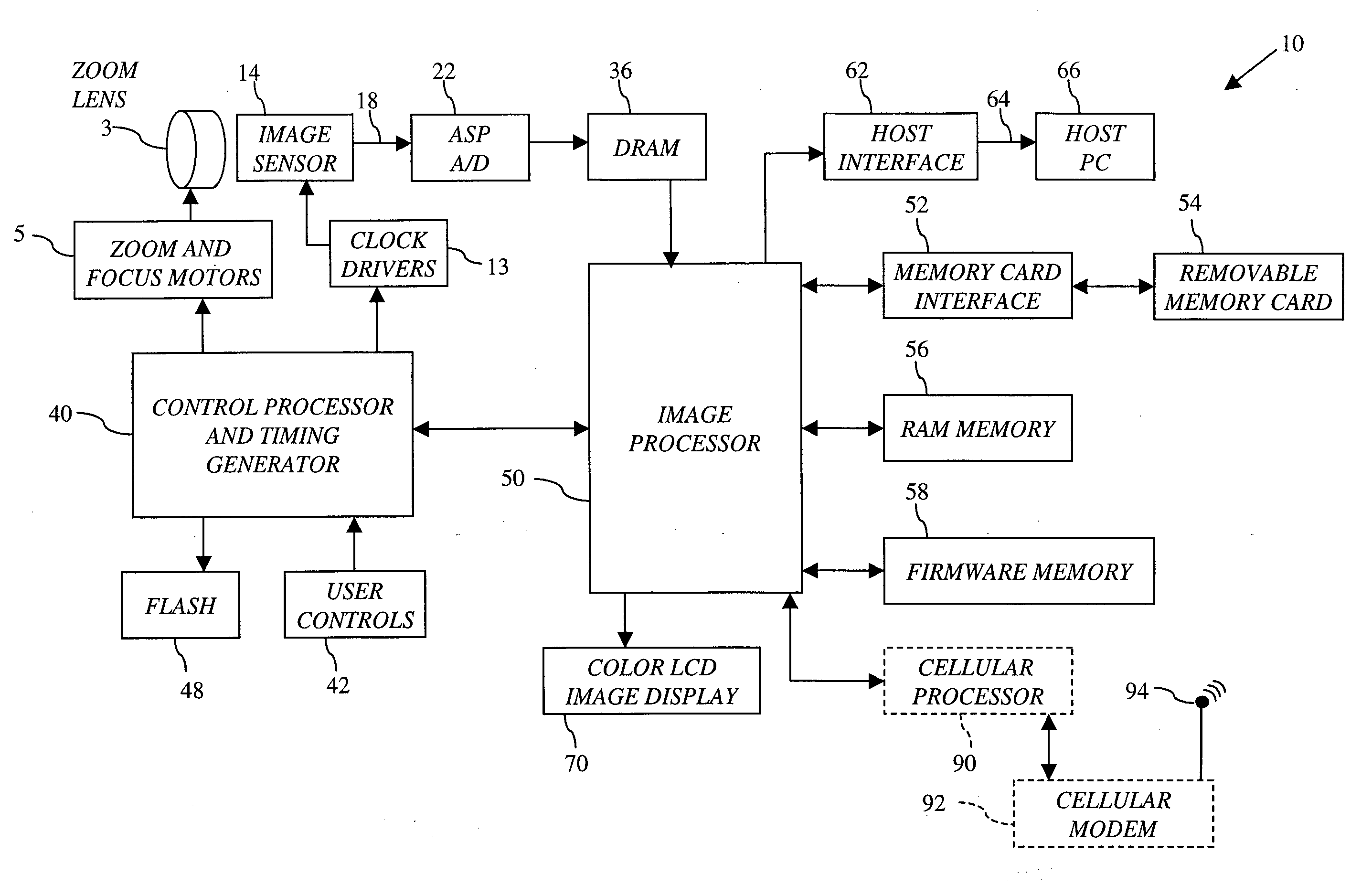
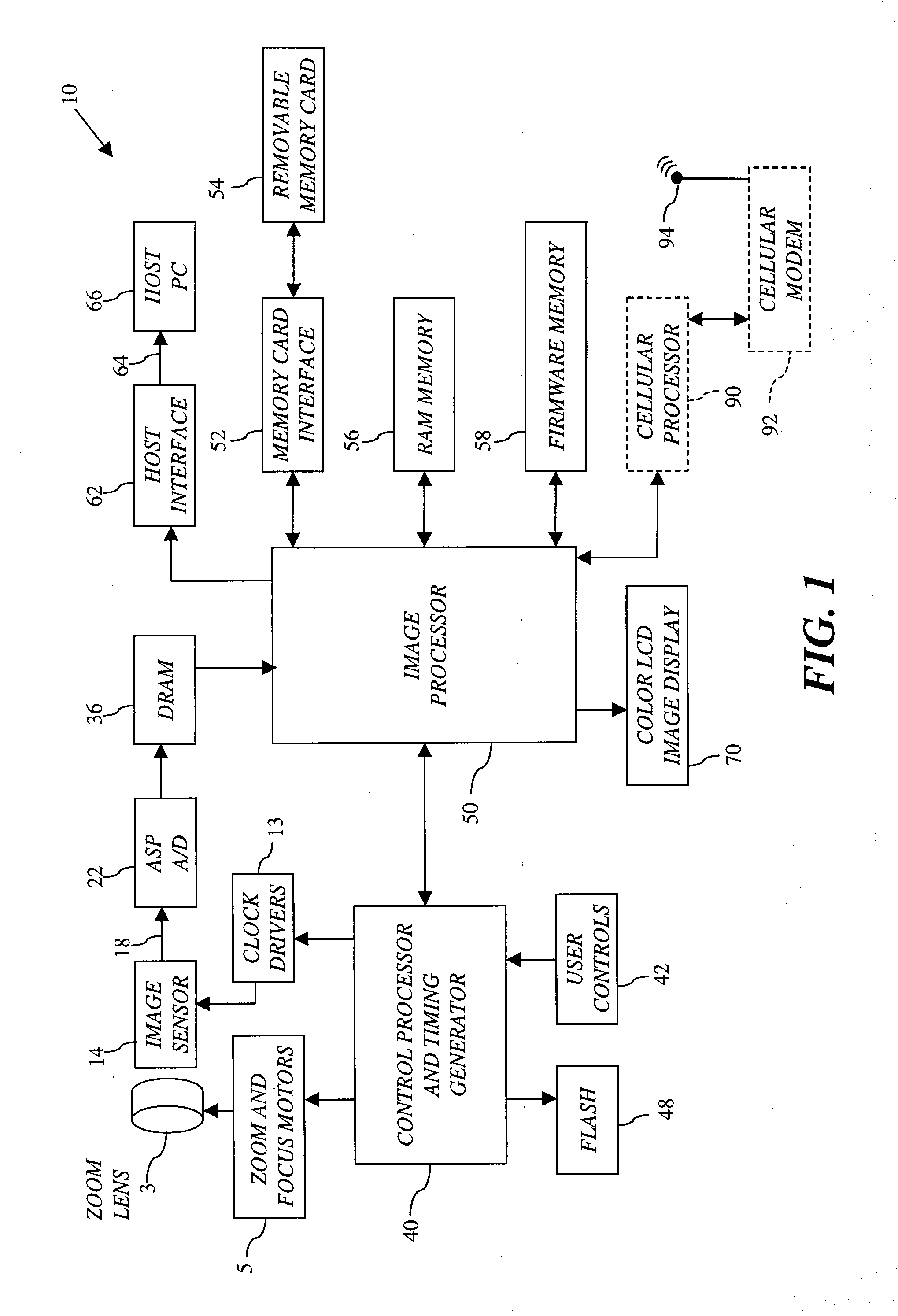
[0032]FIG. 1. depicts a block diagram of an example of a digital imaging device 10, according to an embodiment of the present invention. Digital imaging device 10 is a portable battery operated device, small enou...


PUM


Abstract

A system and method for determining and correcting for imaging device motion during an exposure is provided. According to various embodiments of the present invention, multiple sets of image pixels are defined on an image sensor, where each set of pixels is at least partially contained in the output image area of the image sensor. Signals from each set of image pixels are read out once or more during an exposure, motion estimates are computed using signal readouts from one or more sets of image pixels, and signal readouts from one or more sets of the image pixels are processed to form the final output image.

Description

FIELD OF THE INVENTION[0001]This invention relates to imaging device motion that occurs during the exposure of an image. In particular, embodiments of the present invention pertain to digital signal processing methods that determine and correct for imaging device motion occurring during the exposure of an image.BACKGROUND OF THE INVENTION[0002]Current digital cameras suffer from poor performance in low-light situations, when either a flash is not available, or is not beneficial. Exposure time can be increased to boost the number of photons reaching the sensor, but this solution typically reduces sharpness in the image if there is any motion in the scene or if the camera is not held absolutely steady. Digital cameras can also artificially boost the light intensity with a digital gain factor. The gain factor effectively scales upward the output codevalue for each pixel. The problem with this technique is that it amplifies noise as well as signal content. Low-light images typically hav...

Claims


Application Information

Patent Timeline
Patent Type & Authority Applications(United States)
IPC IPC(8): H04N5/228
CPCH04N5/23248H04N5/23264H04N5/23254H04N23/682H04N23/6811H04N23/68
Inventor BORDER, JOHN N.ANDERSON, TODD J.DEEVER, AARON T.
Owner OMNIVISION TECH INC
Why Eureka
Try Eureka