Anti motion blur display

a technology of motion blur and display screen, applied in the field of anti motion blur display, can solve the problems of unfavorable dynamic behavior of display screen, noise modulation, and inability to improve significant detail of filtering, and achieve the effect of reducing noise modulation, reducing noise, and improving picture quality

Inactive Publication Date: 2005-08-16
KONINKLIJKE PHILIPS ELECTRONICS NV
View PDF5 Cites 78 Cited by
  • Summary
  • Abstract
  • Description
  • Claims
  • Application Information

AI Technical Summary

Benefits of technology

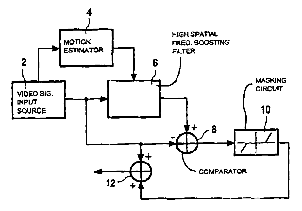
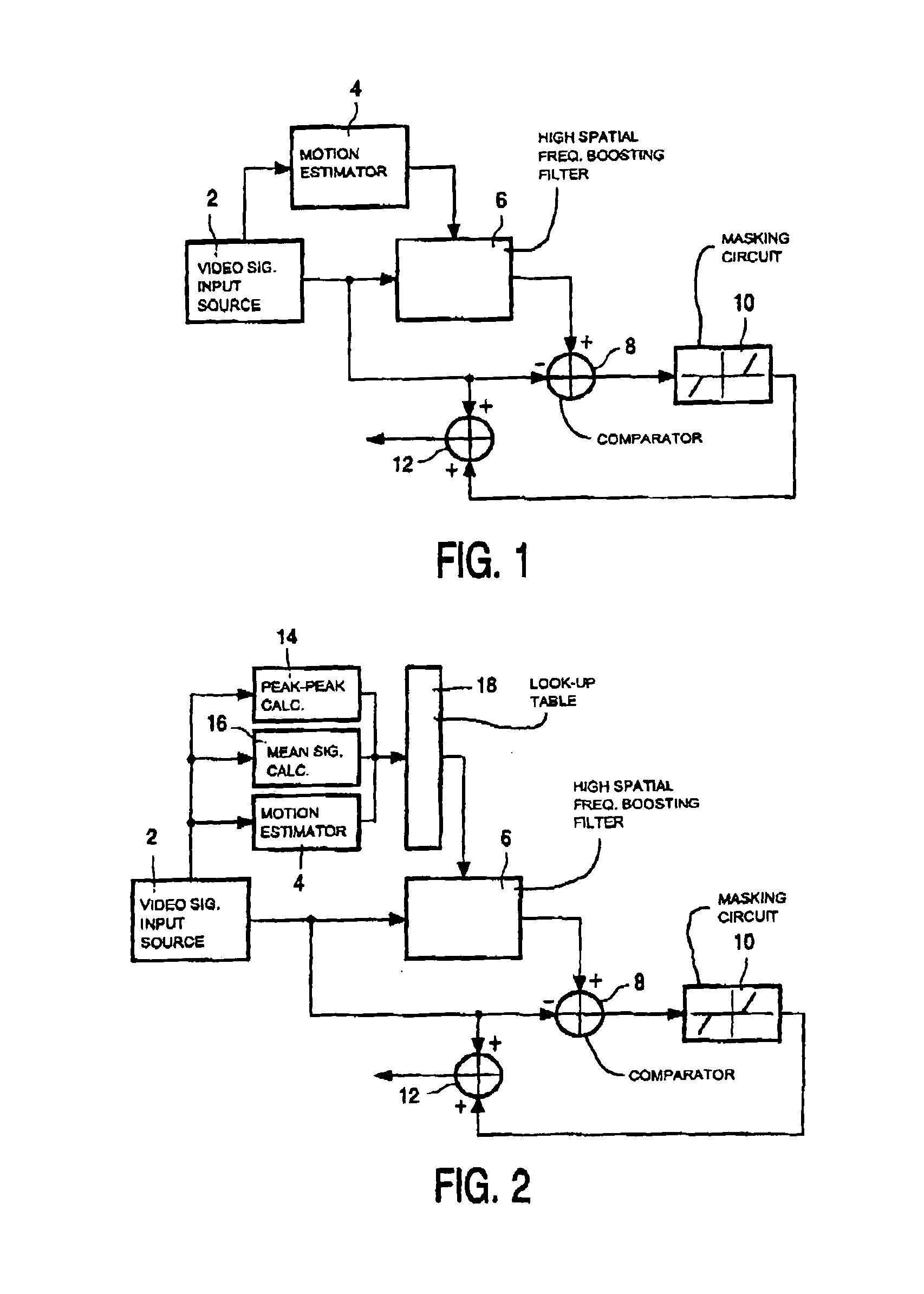
[0008]To solve the object of the invention, it is proposed that the enhancement filter further depends on image characteristics determining high spatial frequency properties of said video signal. By using further image properties, in particular, local image characteristics, which determine high spatial frequencies, filtering in flat regions of the image, e.g., undetailed areas, can be avoided. This filtering may be carried out by second filtering means as well as enhanced first filtering means. The calculation or estimation of the motion vector may then contain slight errors. These error

Problems solved by technology

A drawback of the proposed solution is that in areas where the motion vector is not reliable, i.e., in areas where there is little contrast, filtering may be carried out without improving the picture.
Furthermore, th

Method used


Image

  • Anti motion blur display
  • Anti motion blur display
  • Anti motion blur display

Examples


Embodiment Construction

[0018]In cathode ray tubes, each pixel of a displayed image is generated as a pulse, which is very short compared to the picture time. Different to cathode ray tubes, in new flat, high quality, low cost displays devices, each pixel is displayed during most of the picture time. In case any part of the picture contains motion, the viewer will track this motion. As each pixel is displayed substantially the whole picture time, the intensity of pixels showing the motion is integrated along the motion trajectory as follows: Fout⁡(x→,n)=1ti⁢∫0ti⁢F⁡(x→+tT⁢D→,n)⁢ ⁢ⅆt(1)

where ti is the display time, F is the input video signal, Fout is the output video signal, and T is the picture period. The vector D is the product of the object velocity and the picture period. In case ti is constant, the integration is the same as a convolution of F(x,n) and a sample-and-hold function h(x): Fout⁡(x→,n)=⁢Tti⁢∫0tiT⁢F⁡(x→+α⁢ ⁢D→,n)⁢ ⁢ⅆα=⁢∫-∞∞⁢F⁡(x→+α⁢ ⁢D→,n)⁢h1⁡(α⁢ ⁢D→)⁢ ⁢ⅆα=⁢F⁡(x→,n)*h⁡(x→)(2)

where h(x) is: h...


PUM


Abstract

A method, a circuit arrangement and a display device which suppresses motion blur due to motion integration carried out along a motion trajectory on the image data, which occurs in matrix type displays in which a motion trajectory is integrated by the viewer and/or the display, includes an inverse integration filtering of the video signal. To avoid de-blurring in image regions where motion cannot be detected, or image is low and to avoid noise modulation, motion estimation as well as further image characteristic are used.

Description

BACKGROUND OF THE INVENTION[0001]1. Field of the Invention[0002]The invention relates to a method for reducing motion blur of images shown in display devices, in particular, resulting from integration by the viewer of pixel intensities along the motion trajectory, which can be interpreted as a low-pass filtering in the spatial domain, due to motion-dependant spatial low-pass filtering on image data along a motion trajectory, in which motion vectors depending on moving components of an input video signal are calculated, filter coefficients depending on said motion vectors are calculated, said input video signal is filtered depending on said filter coefficients providing a filtered video signal, an output video signal is generated by combining said input video signal and said filtered video signal, and images are generated on said display device depending on said output video signal. The invention further relates to a circuit arrangement providing anti-motion blur function and a non-s...

Claims


Application Information

Patent Timeline
IPC IPC(8): H04N5/208H04N5/21G06T13/00G06T5/20G09G3/20G09G3/36G09G5/36H04N5/205
CPCH04N5/208H04N5/21Y10S348/91H04N5/57
Inventor DE HAAN, GERARDKLOMPENHOUWER, MICHIEL ADRIAANSZOON
Owner KONINKLIJKE PHILIPS ELECTRONICS NV
Why Eureka
Try Eureka