
Method and apparatus for super-resolution of images

a super-resolution, image technology, applied in the field of super-resolution of images, can solve the problems of increased noise, increased cost and complexity of optics and electronics, and inability to achieve ever-increasing image resolution, etc., and achieve the effect of high resolution

Active Publication Date: 2009-09-17
ATI TECH INC
View PDF31 Cites 77 Cited by
  • Summary
  • Abstract
  • Description
  • Claims
  • Application Information

AI Technical Summary

Benefits of technology

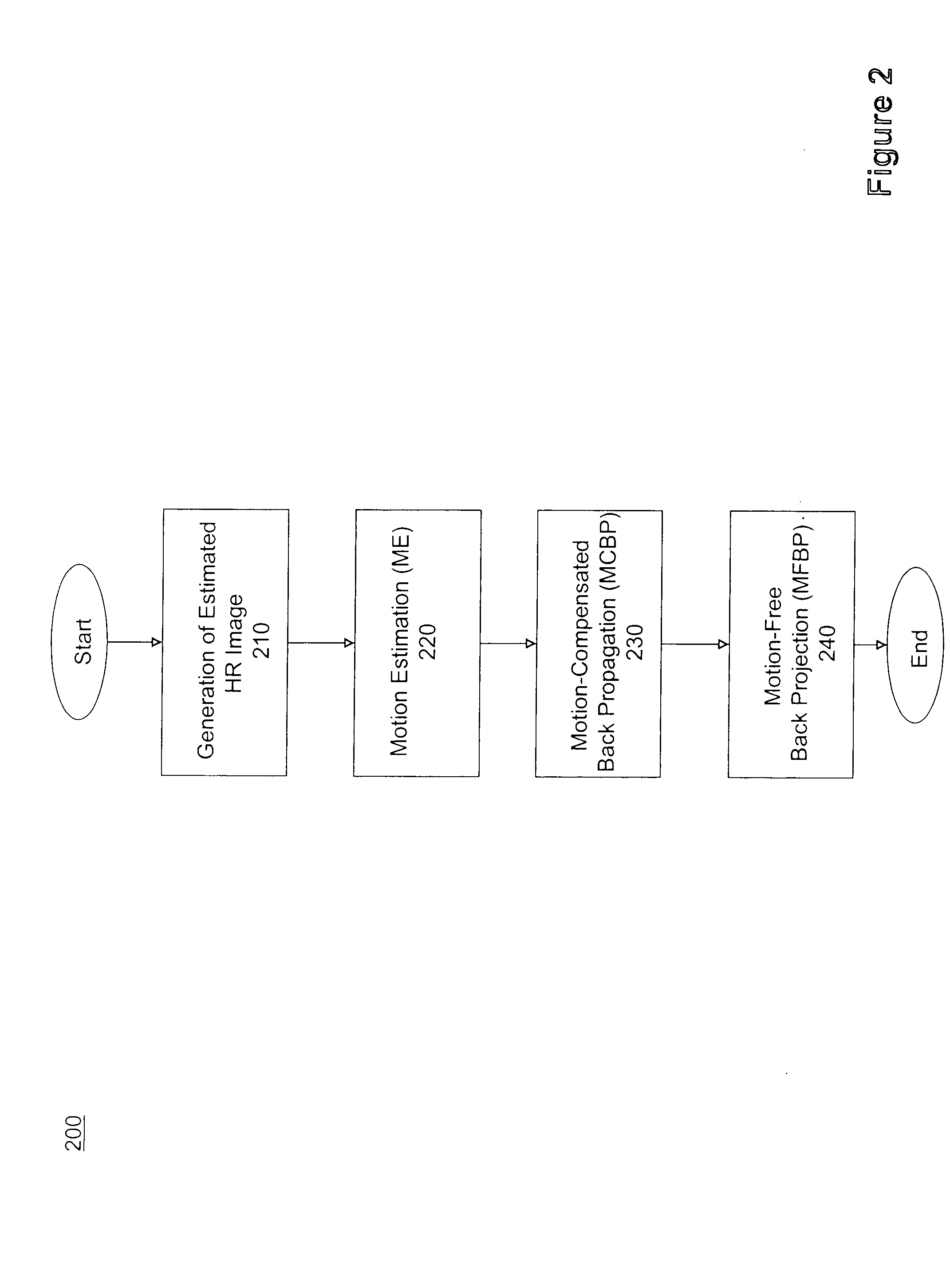
The present invention is a computer-implemented method and system for generating super-resolution images using a sequence of low resolution images. The method involves generating a first estimated high resolution image, motion estimating between the first estimated high resolution image and comparison images from the sequence of low resolution images, motion-compensated back projecting of the first estimated high resolution image, motion-free back projecting of the second estimated high resolution image, and outputting the first super resolved image. The technical effect of the invention is to improve image quality and resolution by generating high quality images from a sequence of low resolution images.

Problems solved by technology

The effort to achieve ever increasing resolution in images runs into issues of cost and complexity in required optics and electronics.
Also, reducing the pixel size in a sensor in order to increase the pixel density of an image, increases the effect of shot noise due to the lower amounts of light available per pixel.
The noise may be due to information lost in image capture, such as low resolution imaging and other forms of electronic, or optical, noise that contribute to the general reduction in correspondence between the image and the actual scene.
The use of pixels in a single image frame to derive additional pixels for the high resolution image, generally results in a blurred image.
H represents the natural loss of spatial resolution caused, for example, due to optical distortions, motion blur, noise within the optics or electronics, noise introduced in transmission of the image, and insufficient sensor density.
Each one of these methods require a high level of computational complexity.

Method used


Image

  • Method and apparatus for super-resolution of images
  • Method and apparatus for super-resolution of images
  • Method and apparatus for super-resolution of images

Examples


Embodiment Construction

[0027]While the present invention is described herein with illustrative embodiments for particular applications, it should be understood that the invention is not limited thereto. Those skilled in the art with access to the teachings provided herein will recognize additional modifications, applications, and embodiments within the scope thereof and additional fields in which the invention would be of significant utility.

[0028]It would be apparent to one of skill in the art that the present invention, as described below, may be implemented in many different embodiments of software (which may include hardware description language code), hardware, firmware, and / or the entities illustrated in the figures. Any actual software code with the specialized control of hardware to implement the present invention is not limiting of the present invention. Thus, the operational behavior of the present invention will be described with the understanding that modifications and variations of the embodi...


PUM


Abstract

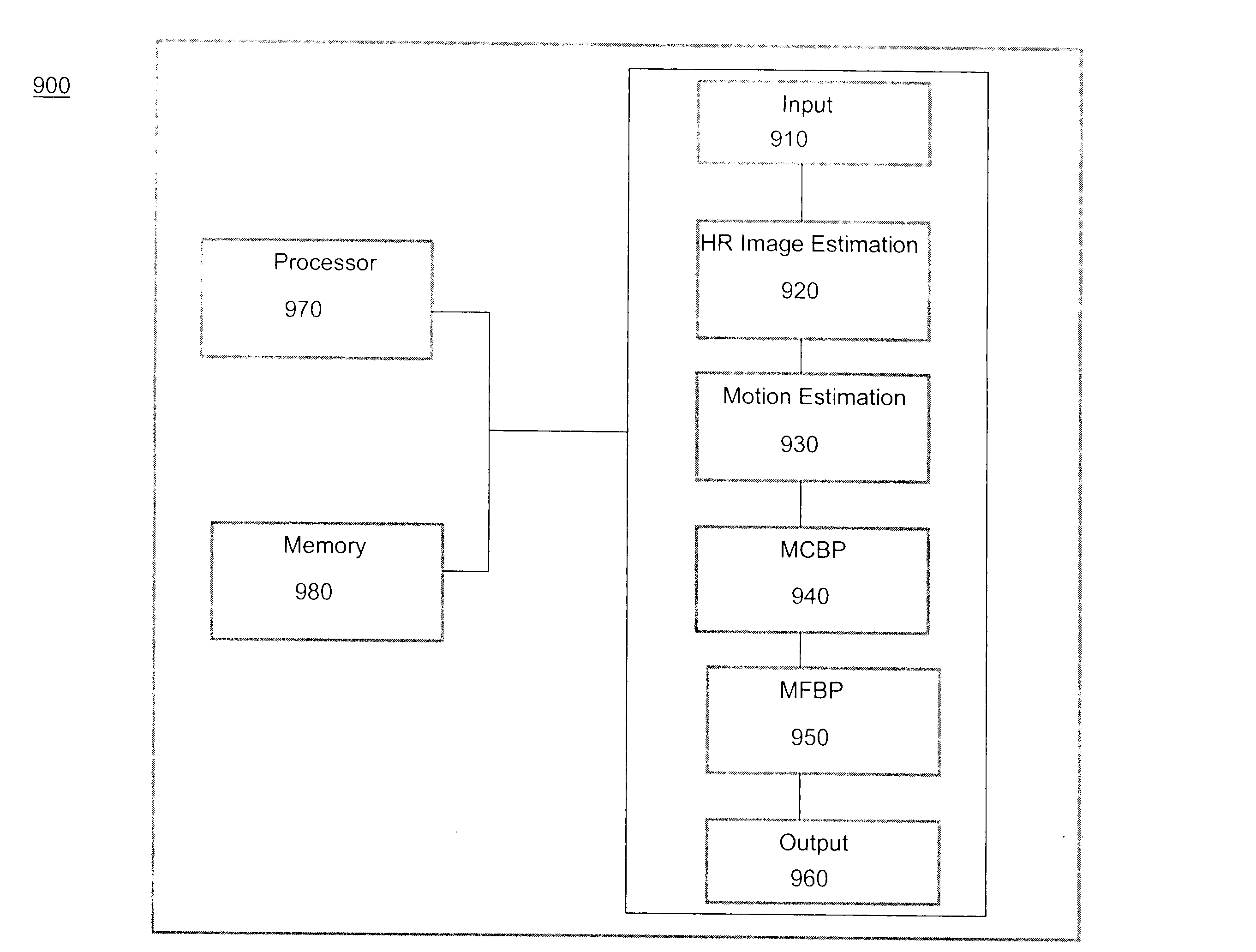
A method to generate super-resolution images using a sequence of low resolution images is disclosed. The method includes generating an estimated high resolution image, motion estimating between the estimated high resolution image and comparison images from the sequence of low resolution images, motion-compensated back projecting, and motion-free back projecting that results in a super resolved image. A corresponding system for generating super-resolution images includes a high resolution image estimation module, a motion estimating module, a motion-compensated back projection module, a motion-free back projection module, an input interface, and an output interface.

Description

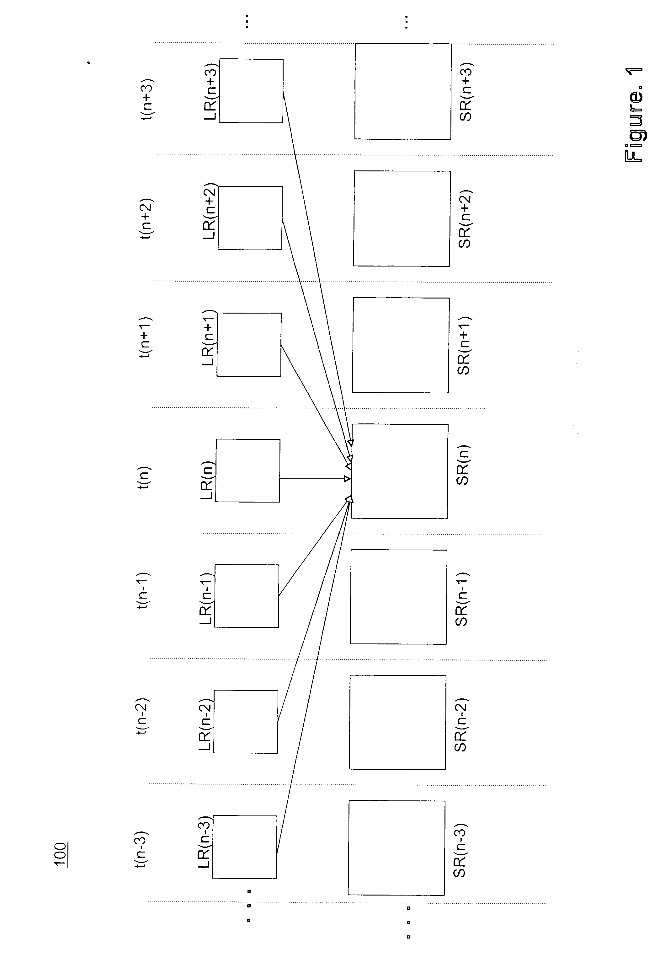
BACKGROUND[0001]1. Field of Invention[0002]The present invention relates generally to super-resolution of images.[0003]2. Related Art[0004]Many applications, for example, such as high-definition television, forensic imaging, surveillance imaging, satellite imaging, medical and scientific imaging, use increasing amounts of resolution with great benefit. The effort to achieve ever increasing resolution in images runs into issues of cost and complexity in required optics and electronics. Also, reducing the pixel size in a sensor in order to increase the pixel density of an image, increases the effect of shot noise due to the lower amounts of light available per pixel.[0005]By way of background, a video signal is a continuous flow of image frames. Each frame captures a temporal instant of a particular scene. The image frames may also have spatial differences between them, either due to motion of the camera or motion in a scene that is captured. Each image, for example, such as a low res...

Claims


Application Information

Patent Timeline
Patent Type & Authority Applications(United States)
IPC IPC(8): H04N11/02
CPCG06T3/4053
Inventor JIA, YUNWEI
Owner ATI TECH INC
Learn More