Image sensing apparatus and image capturing system

a technology of image sensing and image capturing, which is applied in the direction of color television details, television system details, television systems, etc., can solve the problems of long time required for reading out signals from all pixels of the pixel array, the signal read out from the pixel array may reach the upper limit of the dynamic range and become saturated, and the frame period for obtaining the signals of the whole image may be very long, so as to increase the frame rate of reading

Active Publication Date: 2009-01-22
CANON KK
View PDF15 Cites 81 Cited by
  • Summary
  • Abstract
  • Description
  • Claims
  • Application Information

AI Technical Summary

Benefits of technology

[0014]The aim of the present invention is to increase the frame rate in reading out a signal from a pixel array, and to obtain an image by a signal accumulat

Problems solved by technology

In movie shooting using such an image sensing apparatus, the time required for reading out signals from all pixels of the pixel array is long because of the large number of pixels.
More specifically, a signal read out from the pixel array may reach the upper limit of the dynamic range and become saturated.
If the technique of Japanese Patent Laid-Open No. 2001-346096 or 2003-143485 is applied to an image sensing apparatus having 10,000,000 pixel

Method used


Image

  • Image sensing apparatus and image capturing system
  • Image sensing apparatus and image capturing system
  • Image sensing apparatus and image capturing system

Examples


Embodiment Construction

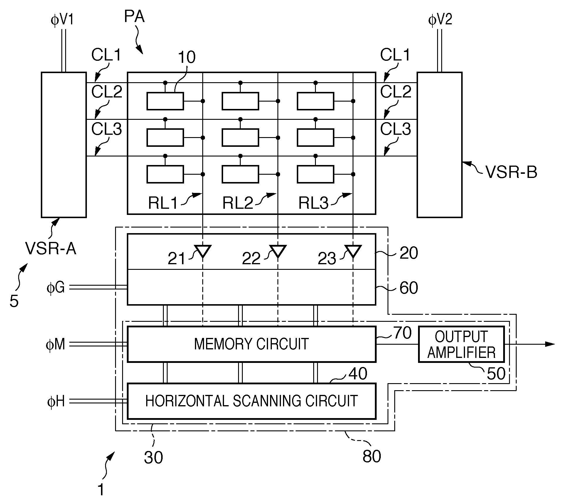
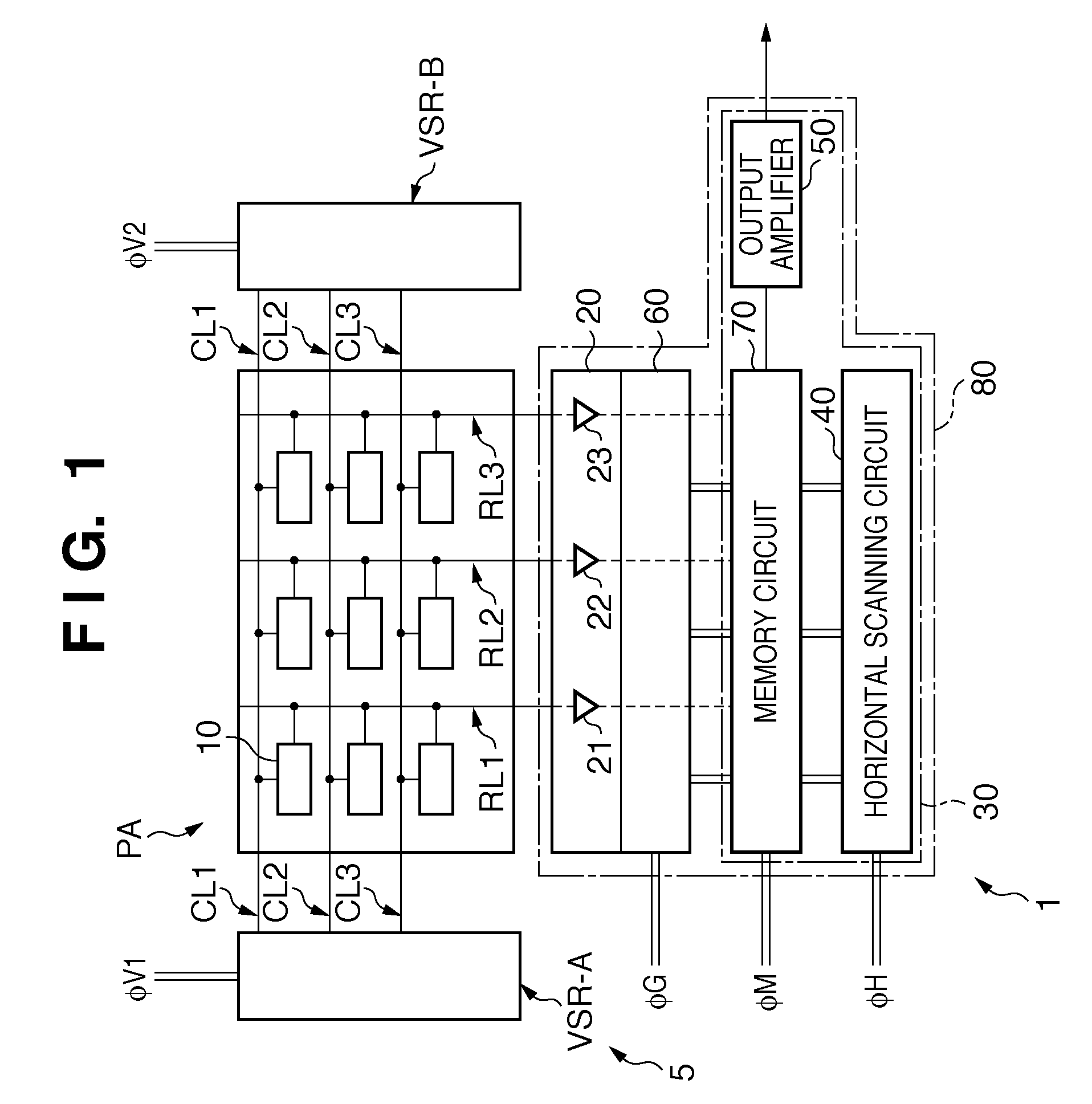
[0038]The schematic arrangement and the operation of an image sensing apparatus 1 according to the first embodiment of the present invention will be described with reference to FIG. 1. FIG. 1 is a block diagram showing the arrangement of the image sensing apparatus 1 according to the first embodiment of the present invention. In FIG. 1, each of control signals φV1, φV2, φG, φM, and φH is shown as one pulse, though they may include a plurality of pulses.

[0039]The image sensing apparatus 1 includes a pixel array PA, selection unit 5, and readout unit 80. The image sensing apparatus 1 has a thinning-out readout mode for reading out signals from some pixels of the pixel array PA.

[0040]In the pixel array PA, a plurality of pixels 10 are arrayed in the row and column directions. FIG. 1 shows a pixel array having 3 rows×3 columns. For the descriptive convenience, a pixel array having 3 rows×3 columns is illustrated here. In fact, the pixel array often includes a larger number of pixels, as...


PUM


Abstract

An image sensing apparatus comprises: a pixel array; a selection unit which selects a readout region in the pixel array; and a readout unit which reads out a signal from the readout region, wherein in thinning-out readout, the readout unit reads out signals from a first readout region corresponding to the whole pixel array at a first pixel density in a first frame period and reads out signals from a second readout region corresponding to a part of the pixel array at a second pixel density in a second frame period, the second pixel density being higher than the first pixel density, and in thinning-out readout, the selection unit causes pixels in the first readout region to perform a charge accumulation operation for a first accumulation period and causes pixels in the second readout region to perform the charge accumulation operation for a second accumulation period.

Description

BACKGROUND OF THE INVENTION[0001]1. Field of the Invention[0002]The present invention relates to an image sensing apparatus and an image capturing system.[0003]2. Description of the Related Art[0004]Recently, image sensing apparatuses having 10,000,000 pixels or more are widely used. In movie shooting using such an image sensing apparatus, the time required for reading out signals from all pixels of the pixel array is long because of the large number of pixels. This decreases the number of sensed images per second (lowers the frame rate).[0005]To prevent this, a technique has been proposed in which the time of signal readout from the pixel array is shortened by skipping and without reading out signals from some of the pixels of the pixel array (performing thinning-out readout) (Japanese Patent Laid-Open No. 9-214836). This technique makes it possible to increase the number of sensed images per second (increase the frame rate).[0006]On the other hand, there is a demand for widening t...

Claims


Application Information

Patent Timeline
IPC IPC(8): H04N5/335H04N5/235H04N5/341H04N5/345H04N5/374
CPCH04N5/3456H04N5/37457H04N5/35572H04N5/353H04N25/445H04N25/53H04N25/587H04N25/778
Inventor HASHIMOTO, SEIJIOTA, KEISUKEOHYA, TAKERUSHIGETA, KAZUYUKI
Owner CANON KK
Why Eureka
Try Eureka