Position/orientation measurement method and apparatus

a technology of position/orientation measurement and measurement method, which is applied in the field of method and apparatus for measuring the position and orientation of objects, can solve the problem of restricting the requirement that indices always be captured, and achieve the effect of high stability and precision

Inactive Publication Date: 2009-01-22
CANON KK
View PDF7 Cites 87 Cited by
  • Summary
  • Abstract
  • Description
  • Claims
  • Application Information

AI Technical Summary

Benefits of technology

[0028]According to the position/orientation measurement apparatus of the present invention, since the position and orientation of a measurement target object can be measured by a better method in consideration of not only the number of detected indices but also an evaluation value associated with their range of distribution, measurements with high stab

Problems solved by technology

However, using this approach, there is a restri

Method used


Image

  • Position/orientation measurement method and apparatus
  • Position/orientation measurement method and apparatus
  • Position/orientation measurement method and apparatus

Examples


first embodiment

[0056]A position / orientation measurement apparatus according to this embodiment measures the positions and orientations of an image capture device and a measurement target object. The position / orientation measurement apparatus and position / orientation measurement apparatus according to this embodiment will be described hereinafter.

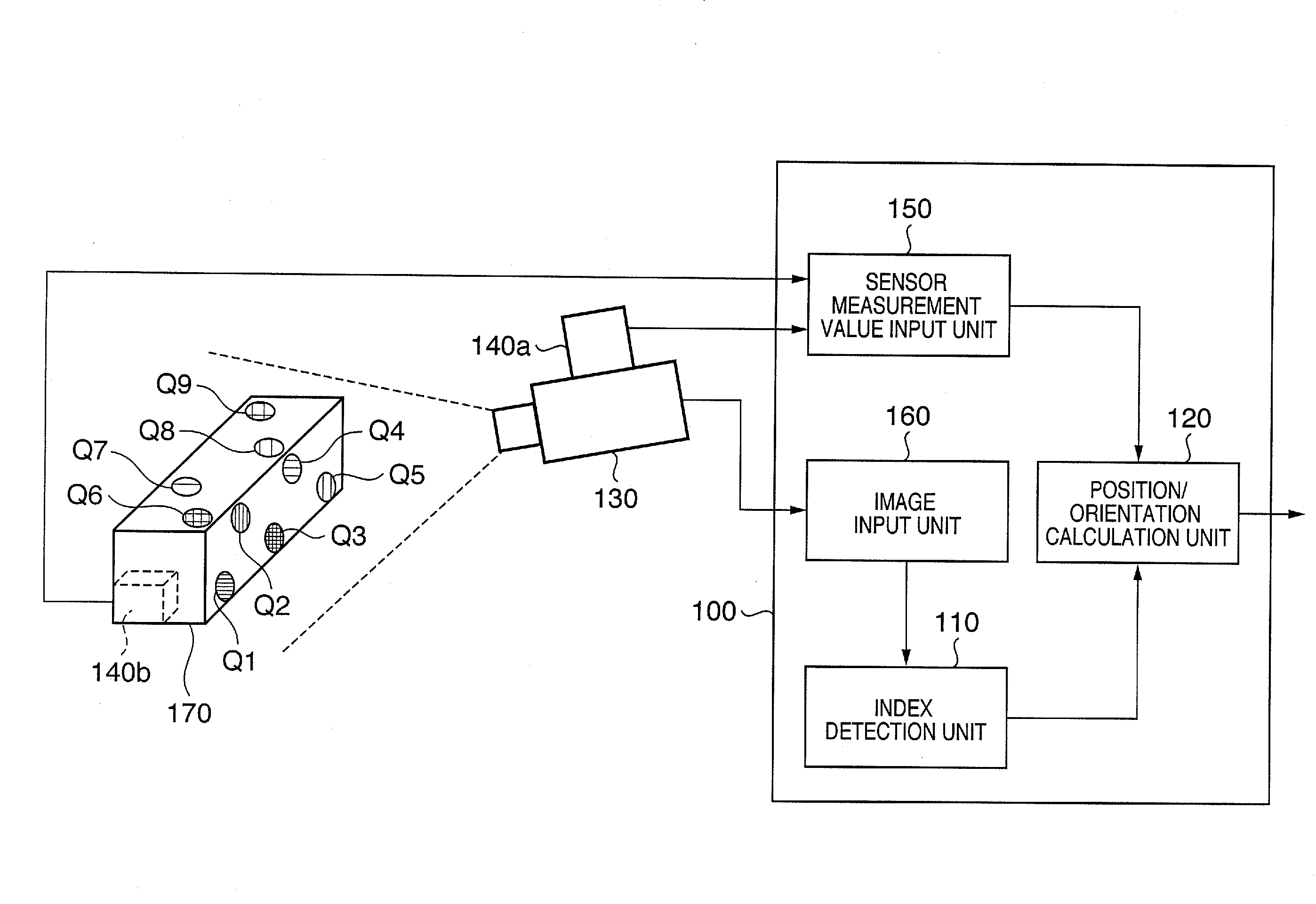
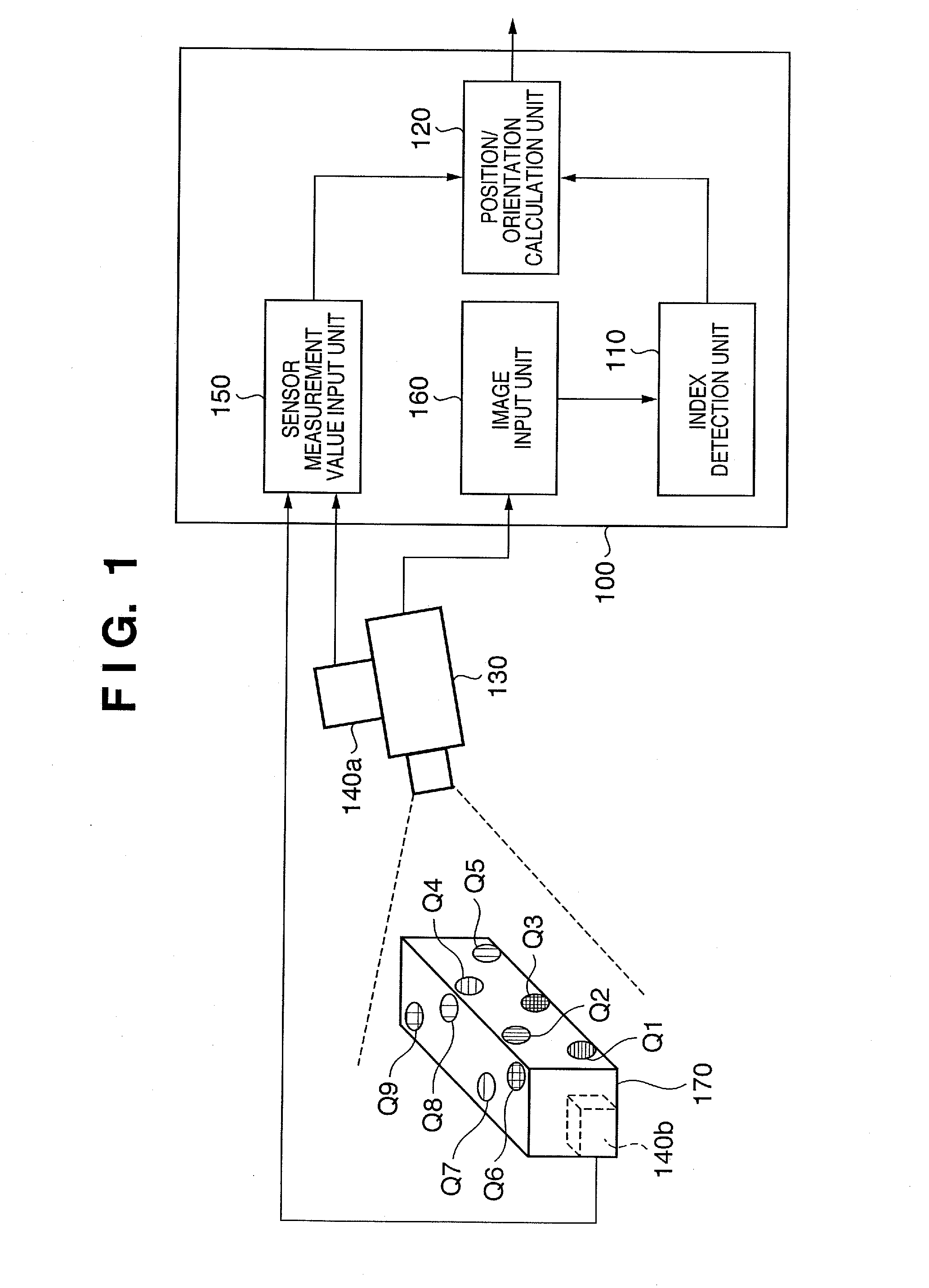
[0057]FIG. 1 shows the arrangement of a position / orientation measurement apparatus according to this embodiment. As shown in FIG. 1, a position / orientation measurement apparatus 100 according to this embodiment comprises an image input unit 160, index detection unit 110, sensor measurement value input unit 150, and position / orientation calculation unit 120. The apparatus 100 is connected to an image capture device 130, and position / orientation sensors 140, that is, sensors 140a and 140b, attached to the image capture device 130 and an object 170 to be measured.

[0058]A plurality of indices Qk (k=1, 2, . . . , K) whose positions on an object coordinate syste...

second embodiment

[0138]A position / orientation measurement apparatus according to this embodiment measures the position and orientation of an arbitrary measurement target object on a reference coordinate system defined in a room or the like.

[0139]The position / orientation measurement apparatus according to this embodiment is different from that of the first embodiment in that no position / orientation sensor is attached to the image capture device, and the image capture device is fixed at a known position and orientation using a tripod or the like. Only differences from the first embodiment will be described below.

[0140]FIG. 12 is a block diagram showing the arrangement of the position / orientation measurement apparatus of this embodiment. As shown in FIG. 12, a position / orientation measurement apparatus 1200 of this embodiment comprises an image input unit 160, index detection unit 110, sensor measurement value input unit 150, and position / orientation calculation unit 1220, and is connected to an image ...

third embodiment

[0148]A position / orientation measurement apparatus according to this embodiment measures the position and orientation of an image capture device on a space such as a room or the like. The position / orientation measurement apparatus according to this embodiment will be described hereinafter.

[0149]In this embodiment, no measurement target object other than the image capture device exists, and the position / orientation measurement apparatus according to this embodiment measures only the position and orientation of the image capture device unlike in the first embodiment. Only differences from the first embodiment will be explained below.

[0150]FIG. 13 is a block diagram showing the arrangement of a position / orientation measurement apparatus of this embodiment. As shown in FIG. 13, a position / orientation measurement apparatus 1300 of this embodiment comprises an image input unit 160, index detection unit 110, sensor measurement value input unit 150, and position / orientation calculation unit...


PUM


Abstract

This invention relates to a position/orientation measurement apparatus which can measure a position and orientation while achieving both high stability and precision. An image including indices laid out on a space is captured, and the indices are detected from the captured image. When a plurality of indices are detected, their distribution range is calculated, and an algorithm to be applied in position/orientation calculations is selected according to the size of the range (S3033, S3050, S3060). For example, when the indices are distributed over a sufficiently broad range, six parameters of the position and orientation of an image capture device are calculated as unknowns (S3070). As the distribution range of the indices becomes smaller, the degrees of freedom of unknown parameters to be calculated are reduced (S3035, S3025).

Description

TECHNICAL FIELD[0001]The present invention relates to a method and apparatus for measuring the position and orientation of an object and, in particular, those of an image capture device.BACKGROUND ART[0002]In recent years, extensive research has been conducted on mixed reality, which aims at seamless merging of physical and virtual spaces. An image display apparatus which presents mixed reality can be implemented as an apparatus which displays an image obtained by superimposing images of a virtual space (virtual objects, text information, and the like rendered by computer graphics), which are generated according to the position and orientation of an image capture device onto an image of a physical space captured by an image capture device such as a video camera or the like.[0003]Essential for implementation of such an image display apparatus, is measurement of a relative position and orientation between a reference coordinate system defined on the physical space (a coordinate system...

Claims


Application Information

Patent Timeline
IPC IPC(8): G06K9/46
CPCG01B21/04G06T2207/30244G06T7/0044G01B21/22G06T7/74
Inventor SATOH, KIYOHIDEUCHIYAMA, SHINJIENDO, TAKAAKIMORITA, KENJI
Owner CANON KK
Why Eureka
Try Eureka