Stimulation system, in particular a cardiac pacemaker

a stimulation system and pacemaker technology, applied in the field of stimulation systems, can solve problems such as undesirable or even fatal physical reactions, material fatigue, and the failure of probes or leads, and achieve the effects of reliable triggering, reliable control, and compact structure of electrode devices

Inactive Publication Date: 2009-01-22
UNIV DUISBURG ESSEN
View PDF25 Cites 137 Cited by
  • Summary
  • Abstract
  • Description
  • Claims
  • Application Information

AI Technical Summary

Benefits of technology

[0015]The electrode device is particularly preferably controlled directly by the time-varying magnetic field. “Direct” control is to be understood in the present patent application in that the electrical impulses are generated in direct dependence on the magnetic field, for example, depending on the magnitude of the magnetic field, the polarity of the magnetic field and / or the rate of change of the magnetic field, particularly preferably without any active electronic component being interposed in the electrode device. Consequently, in the preferred direct control, electrical impulses or stimulations are generated so that they are only temporally correlated to the magnetic field. This also permits a very simple and in particular compact structure of the electrode device and / or a very reliable defined control.
[0016]Another aspect of the present invention includes configuring the electrode device such that an electrical impulse is only generated when a minimum field strength of the magnetic field is exceeded. This very simply permits reliable control which in particular is not sensitive to interference when the minimum field strength is selected as suitably high, since strong magnetic fields occur very rarely but alternating electromagnetic fields having various frequencies are very common.
[0017]According to one aspect of the present invention, the electrode device must first be activated before a further electrical impulse can be generated. This activation is effected in particular by another signal, preferably by the opposite field direction of the magnetic field, shortly before triggering and generating the next electrical impulse. Thus, two-stage triggering or signal generation is required to generate an electrical impulse by means of the electrode device. This two-stage property results in particularly reliable triggering, i.e., not sensitive to interference.
[0018]The aforesaid triggering safety can be further improved or enhanced whereby the activation of the electrode device always takes place shortly before the generation of the next electrical impulse. Accordingly, the possibility that an electrical impulse as a result of an interference signal (external magnetic field with corresponding field orientation and exceeding the minimum field strength) can lead to undesirable or premature triggering of the next electrical impulse is so minimal that there is no risk for a patient.
[0019]According to another aspect of the present invention, a coil device having a high number of turns, that is a coil having many turns, is used to generate an electrical impulse having a high voltage of at least 0.5 V, preferably substantially 1 V or more and having a relatively long duration of at least 0.05 to 2 ms. In this case, the coil device can in particular have a soft-magnetic or ultrasoft magnetic core. The high number of turns, in particular at least 1,000 turns, of a suitably insulated wire made of, for example, Cu, Ag or Al in particular having a diameter of about 0.01 to 0.1 mm permits the generation of a strong and long electrical impulse in said sense.
[0020]According to a further aspect of the present invention, when the magnetic field is switched on, no continuous or persistent, for example, sawtooth-shaped ascending magnetic field pulse is generated by the control device but a plurality of short magnetic field pulses, in particular so that the core of the coil device or electrode device always varies its magnetization far below the saturation state. Thus, a minimal energy consumption can be achieved, in particular if the largest possible temporal flux variation takes place in the core of the coil device or electrode device throughout the entire duration of the stimulating pulse (optionally a contiguous sequence of electrical impulses of the electrode device; in the present invention, this sequence is considered as a single electrical impulse for stimulation). This can be achieved by short magnetic field pulses.

Problems solved by technology

The electrical lead is problematical or disadvantageous.
This runs over a length of about 30 cm in the blood circulation system and can thereby cause undesirable or even fatal physical reactions.
Furthermore, the risk of failure of the probes or leads due to material fatigue as a result of the severe mechanical stressing during body movements is particularly high.
Another complication frequently encountered is dislocation of the probes triggered by movements of the patient.
However, purely magnetic stimulation does not function satisfactorily so that magnetically stimulating cardiac pacemakers have not been generally accepted.
Such cardiac pacemakers with a separate electrode device have not been widely accepted so far.
This may be because the electrode device is of a considerable size and has a limited operating time because of the battery.
Apart from the fact that an external control device is generally problematical and not desirable, the wiring between the implanted coil and the electrodes at a distance therefrom results in the same problems as in the usual cardiac pacemaker described above where at least one electrode is connected to the implanted cardiac pacemaker via an electrical lead through a vein.
Moreover, the implanted coil is very sensitive to external electromagnetic fields so that undesirable interfering voltages are induced and appear at the electrodes.
Such a microstimulator is not suitable for cardiac stimulator or as a cardiac pacemaker since it is relatively large for sufficient capacity and requires an external energy supply.
This is problematic, in particular due to magnetic saturation.

Method used


Image

  • Stimulation system, in particular a cardiac pacemaker
  • Stimulation system, in particular a cardiac pacemaker
  • Stimulation system, in particular a cardiac pacemaker

Examples


Embodiment Construction

[0043]In the figures the same reference numerals are used for the same parts or parts of the same type, components and the like, where corresponding or similar advantages and properties are obtained even if a repeated description is omitted.

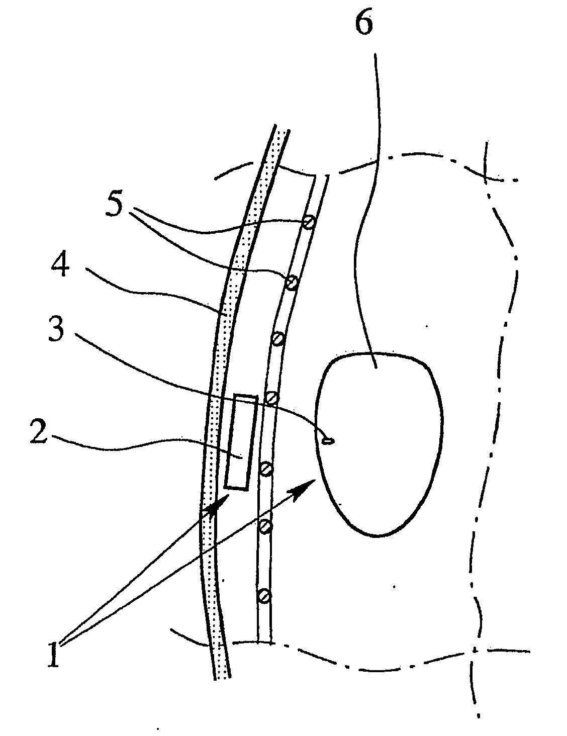
[0044]FIG. 1 is a schematic sectional view of a proposed stimulation system 1 which is in particular configured as or works as a cardiac pacemaker in the example shown. However, the present invention is not restricted to this. For example, the stimulation system 1 can additionally or alternatively operate as a defibrillator or be used for other purposes and at other locations in the human or animal body.

[0045]The stimulation system 1 preferably comprises an implantable control device 2 and an implantable electrode device 3 separate therefrom. In the example shown, the control device 2 is implanted, in particular in the thoracic cage between the skin 4 and the ribs 5.

[0046]The control device 2 can be implanted as in present-day cardiac pacemakers....


PUM


Abstract

A stimulation system, an implantable electrode device and a method for operating an implantable electrode device are proposed. A simplified implantation, a simple construction and reliable control are made possible by the electrode device being supplied with energy, and controlled, in an exclusively wireless manner via a time-variable magnetic field. The magnetic field is generated by an implanted control device.

Description

CROSS-REFERENCE TO RELATED APPLICATION[0001]This application is U.S. CIP National Application under 35 U.S.C. 111(a) and claims priority to PCT Application WO / 2007 / 087875 (PCT / EP2006 / 012193), filed Dec. 18, 2006, which claims priority to German Applications, 10 2006 001 968.7, filed 13.01.2006, 10 2006 007 403.3, filed 17.02.2006 and 10 2006 042 850.1, filed 08.09.2006, all of which are incorporated herein by reference in their entirety.[0002]An exemplary embodiment of the present invention relates to a stimulation system, in particular for a cardiac pacemaker, an implantable electrode device or stimulation device for a stimulation system as well as a method for operating an implantable electrode device or stimulation device, in particular a cardiac pacemaker.[0003]In the following description of the invention, the focus is primarily on a cardiac pacemaker. However, the present invention is not restricted to this particular solution, but in general can be applied to other stimulatio...

Claims


Application Information

Patent Timeline
Patent Type & Authority Applications(United States)
IPC IPC(8): A61N1/362
CPCA61N1/3787
Inventor KISKER, ERHARDWIENEKE, HEINRICH
Owner UNIV DUISBURG ESSEN
Why Eureka
Try Eureka