
Expandable bone device

a bone device and expandable technology, applied in the field of expandable bone devices, can solve the problems of inconvenient control of the expansion of the balloon-like device, the inability to control the expansion direction of the cancellous bone and/or the reduction of the compression fracture, and the inability to reduce the compression fractur

Active Publication Date: 2009-01-22
CORELINK
View PDF4 Cites 284 Cited by
  • Summary
  • Abstract
  • Description
  • Claims
  • Application Information

AI Technical Summary

Benefits of technology

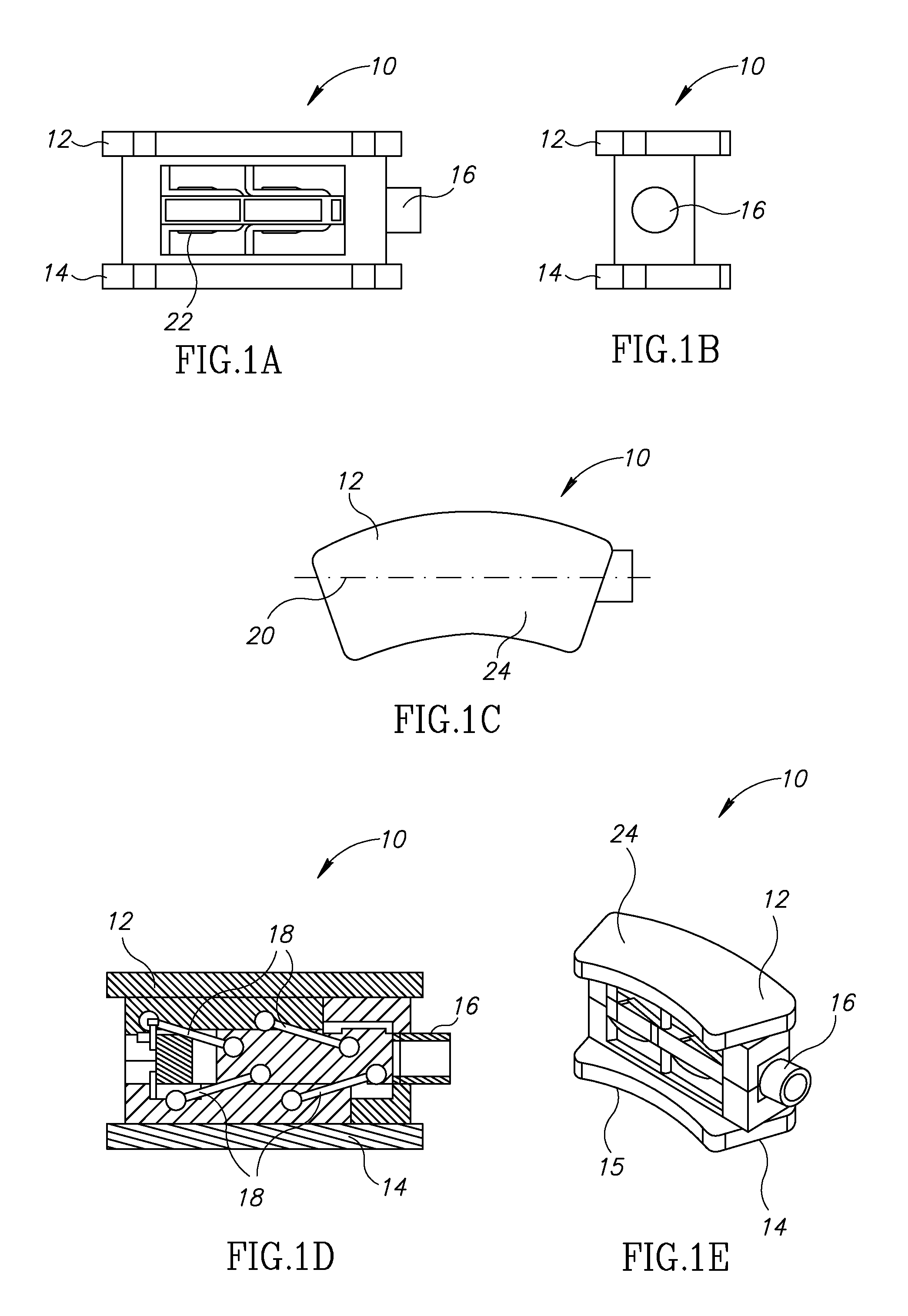
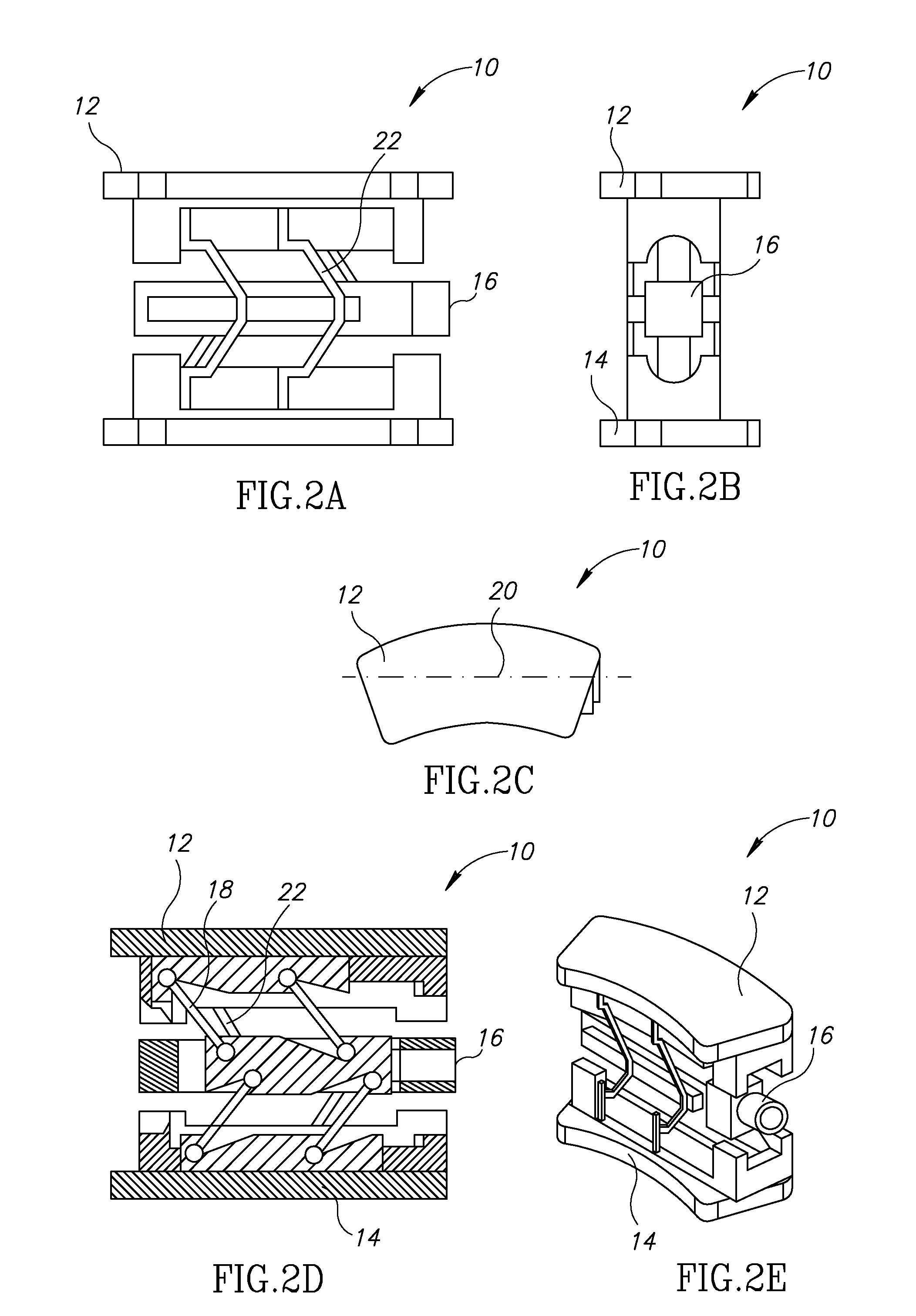
[0007]The expandable bone device may include one or more of the following non-limiting features. For example, in the expanded orientation, the deformable support struts oppose forces directed normal to bone support faces of the first and second bone support elements so as to maintain the first and second bone support elements in the expanded orientation. The deformable support struts pass through a phase of elastic instability when moved by the manipulator from the collapsed orientation to the expanded orientation and vice versa. The link members maintain parallelism between the first and second bone support elements throughout movement between the collapsed and expanded orientations.

Problems solved by technology

Inflation of the balloon-like device causes a compaction of the cancellous bone and / or bone marrow against the inner cortical wall of the bone, thereby resulting in enlargement of the bone cavity and / or reduction of the compression fracture.
However, it has been found that expansion of the balloon-like device is not readily controllable.
As a result, the direction of compaction of the cancellous bone and / or reduction of the compression fracture is not controllable, and expansion occurs in multiple directions and along multiple axes.
The cement may also cause new fractures in adjacent levels.

Method used


Image

  • Expandable bone device
  • Expandable bone device
  • Expandable bone device

Examples


Embodiment Construction

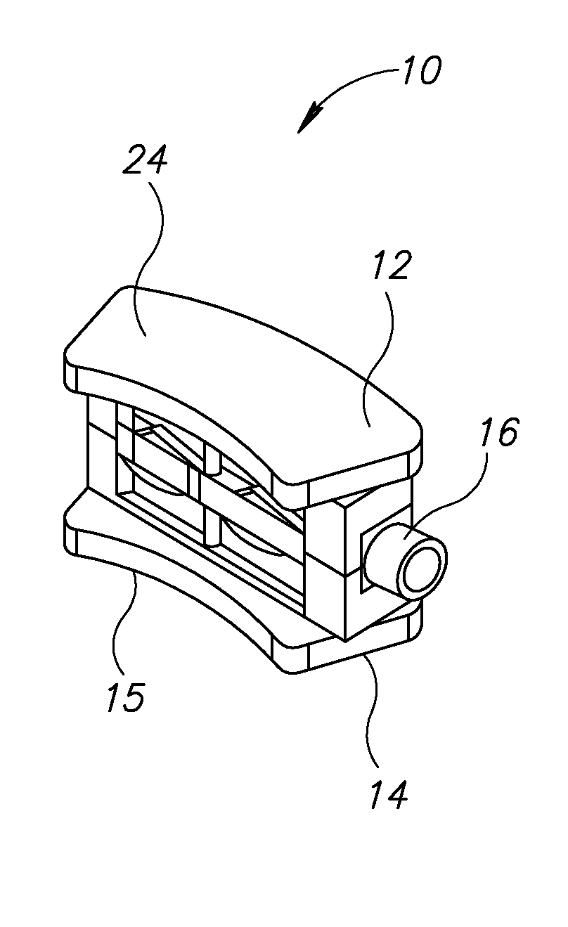
[0014]Reference is now made to FIGS. 1A-1E and FIGS. 2A-2E, which illustrate an expandable bone device 10, constructed and operative in accordance with a non-limiting embodiment of the present invention.

[0015]In the illustrated embodiment, expandable bone device 10 includes first and second bone support elements 12 and 14. A manipulator 16 is positioned between first and second bone support elements 12 and 14 and connected to them by link members 18.

[0016]The expandable bone device 10 may be constructed, without limitation, of medically safe metals (e.g., stainless steel, titanium or titanium alloys, cobalt-chromium or other alloys, shape memory alloys, such as NITINOL), plastics, including PEEK, resorbable materials and shape memory polymers, or bone, such as allograft or bone derivatives, or any combination of the above.

[0017]One or more of first and second bone support elements 12 and 14 may be non-smooth for enhancing adhesion to bone structure. Additionally or alternatively, on...


PUM


Abstract

An expandable bone device including first and second bone support elements, a manipulator positioned between the first and second bone support elements and connected to them by link members, the manipulator adapted to move the first and second bone support elements between a collapsed orientation and an expanded orientation, wherein in the collapsed orientation the first and second bone support elements are drawn towards the manipulator and in the expanded orientation the first and second bone support elements are moved outwards away from a longitudinal axis of the manipulator, and deformable support struts connected between the manipulator and the first and second bone support elements that deform when moved by the manipulator from the collapsed orientation to the expanded orientation and vice versa, wherein in the expanded orientation the deformable support struts form a structure that maintains the first and second bone support elements in the expanded orientation.

Description

FIELD OF THE INVENTION[0001]The present invention relates generally to expandable bone devices, such as but not limited to, devices for vertebral body reconstruction (vertebroplasty), such as for treatment of compression fractures (e.g., the thoracic and lumbar spine area), or for an expandable bone device for transversely or axially displacing structures (e.g., in the spine).BACKGROUND OF THE INVENTION[0002]Various instruments and methods for the treatment of compression-type bone fractures and other osteoporotic and / or non-osteoporotic conditions have been developed. In one method, a cavity may be formed in the bone to be treated, followed by the insertion of an inflatable balloon-like device into the bone cavity. Inflation of the balloon-like device causes a compaction of the cancellous bone and / or bone marrow against the inner cortical wall of the bone, thereby resulting in enlargement of the bone cavity and / or reduction of the compression fracture. The balloon-like device is th...

Claims


Application Information

Patent Timeline
Patent Type & Authority Applications(United States)
IPC IPC(8): A61F2/44
CPCA61B17/8858A61F2/4455A61F2002/30133A61F2002/30471A61F2230/0015A61F2002/3055A61F2220/0025A61F2220/0091A61F2002/30507
Inventor LEVY, MARK M.ZYLBERBERG, EYALSPANIER, YAIRYADIN, AMNONMELOUL, RAPHAEL
Owner CORELINK
Learn More