Method and Arrangements for Audio Signal Encoding

Active Publication Date: 2009-01-22
UNIFY GMBH & CO KG
View PDF3 Cites 48 Cited by
  • Summary
  • Abstract
  • Description
  • Claims
  • Application Information

AI Technical Summary

Benefits of technology

[0026]Furthermore, within the framework of deriving the mixing parameter, the signal level ratio can be converted such that for a predominance of the atonal audio signal proportion the tonal audio signal proportion is reduced

Problems solved by technology

In many contemporary communication systems and especially in mobile communication systems there is only limited transmission bandwidth available for real time audio transmissions, such as speech or music transmissions for example.
However the

Method used


Image

  • Method and Arrangements for Audio Signal Encoding
  • Method and Arrangements for Audio Signal Encoding
  • Method and Arrangements for Audio Signal Encoding

Examples


Example

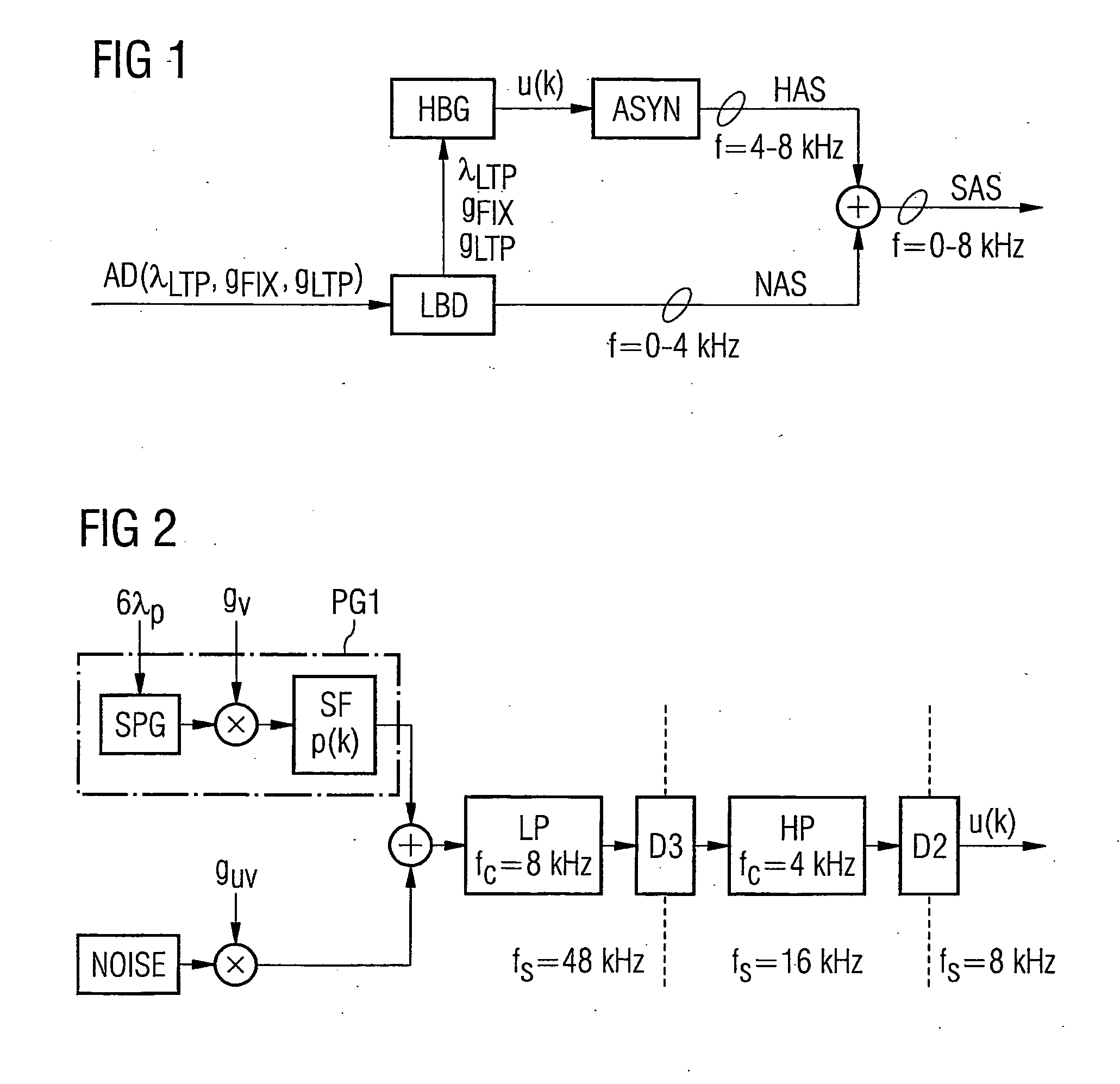
[0071]A first embodiment variant of the excitation signal generator HBG is shown schematically in FIG. 2. The embodiment variant shown in FIG. 2 features a pulse generator PG1, a noise generator NOISE, a lowpass LP with cut-off frequency fc=8 kHz, a decimator D3 with decimation factor m=3 (or generally m=N), a highpass HP with cut-off frequency fc=4 kHz as well as a decimator D2 with decimation factor m=2. The noise generator NOISE preferably creates white noise. The pulse generator PG1 on the one hand includes a square-wave pulse generator SPG and a pulse-shaping filter SF with a predetermined filter coefficient set p(k) of finite length. While the noise generator NOISE is used to create the atonal components of the excitation signal u(k), the pulse generator PG1 contributes to creating the tonal components of the excitation signal u(k).

[0072]The audio parameters gv, guv and λp are derived and adapted for each time frame in a continuous sequence from audio parameters of the lowband...

Example

[0082]A second embodiment variant of the excitation signal generator HBG designed in this way is shown schematically in FIG. 4 and will be explained below. The embodiment variant shown in FIG. 4 features a pulse generator PG2 as well as a noise generator NOISE preferably generating white noise. The pulse generator PG2 on the one hand comprises a pulse positioning device PP as well as a lookup table LOOKUP, in which predetermined pulse shapes vj(k) are stored. While the noise generator NOISE is used for creating the atonal components of the excitation signal u(k), the pulse generator PG2 contributes to creating the tonal components of the excitation signal u(k). Both the noise generator NOISE and also the pulse generator PG2 directly use the target sampling rate of fs=8 kHz.

[0083]The excitation signal generator is supplied with the audio parameters gv, guv and λp for each time frame in a continuous sequence. The derivation of the audio parameters gv, guv and λp has already been expla...


PUM


Abstract

To form an audio signal, frequency components of the audio signal which are allotted to a first subband are formed by means of a subband decoder using supplied fundamental period values which respectively indicate a fundamental period for the audio signal. Frequency components of the audio signal which are allotted to a second subband are formed by exciting an audio synthesis filter using an excitation signal which is specific to the second subband. To produce this excitation signal, an excitation signal generator derives a fundamental period parameter from the fundamental period values. The fundamental period parameter is used by the excitation signal generator to form pulses with a pulse shape which is dependent on the fundamental period parameter at an interval of time which is determined by the fundamental period parameter and to mix them with a noise signal.

Description

CROSS REFERENCE TO RELATED APPLICATIONS[0001]This application is the US National Stage of International Application No. PCT / EP2006 / 000812, filed Jan. 31, 2006 and claims the benefit thereof, which is incorporated by reference herein in their entirety.FIELD OF THE INVENTION[0002]The invention relates to a method and arrangements for audio signal encoding. In particular the invention relates to a method and an audio signal decoder for forming an audio signal as well as to an audio signal encoder.BACKGROUND OF THE INVENTION[0003]In many contemporary communication systems and especially in mobile communication systems there is only limited transmission bandwidth available for real time audio transmissions, such as speech or music transmissions for example. In order to transmit as many audio channels as possible over a transmission link with restricted bandwidth, such as a radio network for example, there is therefore frequently provision for compressing the audio signals to be transmitt...

Claims


Application Information

Patent Timeline
IPC IPC(8): G10L19/00G10L19/02G10L21/038
CPCG10L21/038G10L19/0208
Inventor GARTNER, MARTINGEISER, BERNDJAX, PETERSCHANDL, STEFANTADDEI, HERVEVARY, PETER
Owner UNIFY GMBH & CO KG
Why Eureka
Try Eureka