
Image processing apparatus

Inactive Publication Date: 2006-02-21
MINOLTA CO LTD
View PDF15 Cites 9 Cited by
  • Summary
  • Abstract
  • Description
  • Claims
  • Application Information

AI Technical Summary

Benefits of technology

[0014]The object of the present invention is to provide an image processing apparatus that can support a high definition with an inexpensive and simple configuration and can improve a reproducing quality of black letters or lines.
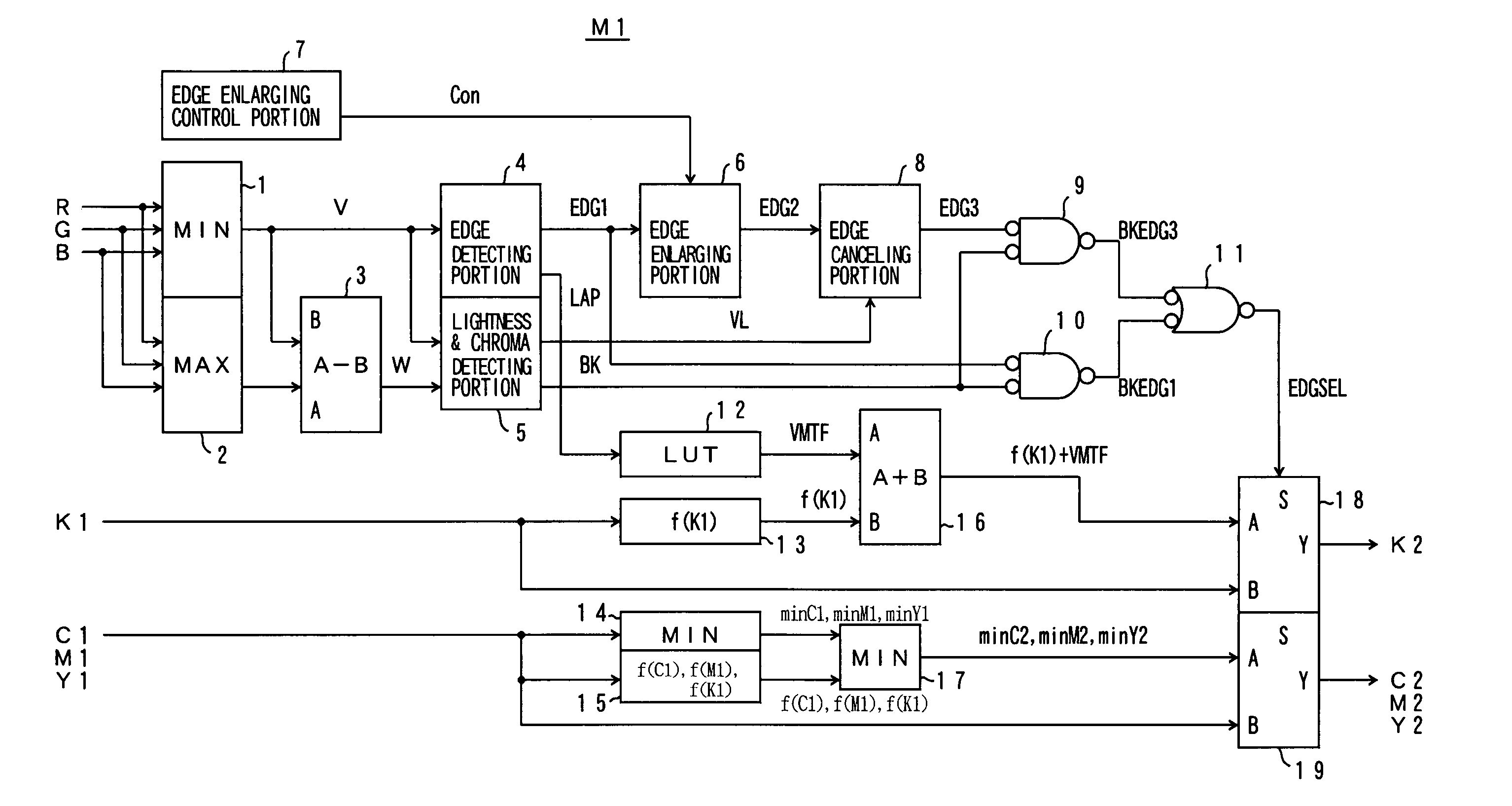
[0015]According to the preferred embodiment of the present invention, the image processing apparatus includes an edge detecting portion for detecting an edge area in an input image and a lightness and chroma detecting portion for detecting a low lightness and low chroma area of the input image. The image processing apparatus performs an image processing (such as edge emphasizing) for the edge area of black letters or lines decided by the detection signals of the edge detecting portion and the chroma detecting portion. The image processing apparatus includes an edge enlarging portion for enlarging the edge area detected by the edge detecting portion, and means for increasing or decreasing a density of each color in the enlarged edge area. According to this process, a color drift in the edge portions becomes inconspicuous, so that the reproducing quality of the black letters or lines is improved.
[0016]According to a more preferable embodiment, the image processing apparatus includes an edge enlarging portion for enlarging the edge area detected by the edge detecting portion, and means for converting image data of each color component so that densities of color components in the enlarged edge area, e.g., a densities of color components C, M, Y are decreased, and a density of a black component, e.g., a density of color component B is increased.

Problems solved by technology

However, along with a recent high definition of the image reader, the conventional image processing explained above is not sufficient for suppressing color drift and improving the reproducing quality of the black letters or lines.
However, in this case, a capacity of memory necessary for storing the image data will also increase along with the increase of the matrix size, and the cost will increase substantially.

Method used


Image

  • Image processing apparatus
  • Image processing apparatus
  • Image processing apparatus

Examples


first embodiment

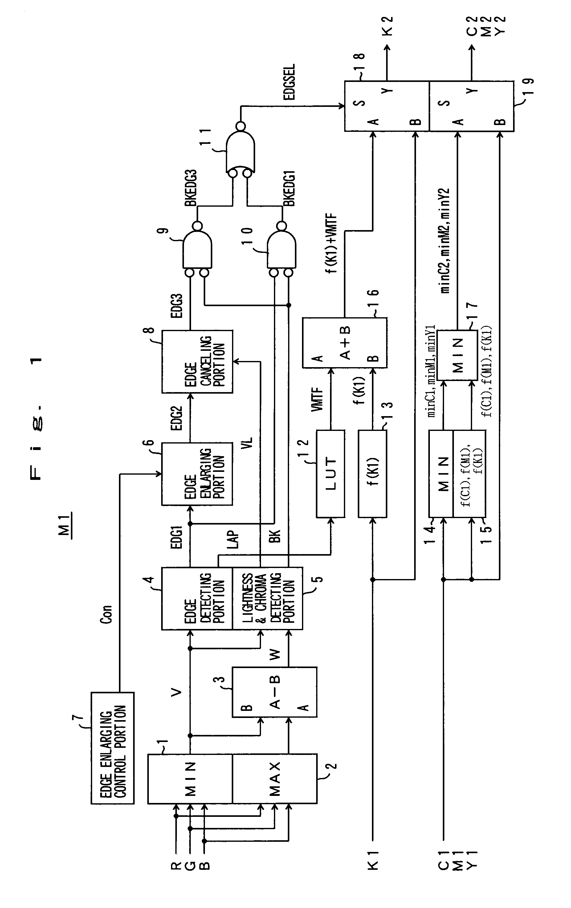
[0029]An image processing apparatus M1 shown in FIG. 1 is mounted in a digital color copying machine for example. The color copying machine is equipped with an image reading device that includes a CCD image sensor and its drive system (not shown). In the image reading device, three primary colors of input image signals (color picture signals) R, G and B are obtained by scanning an original image as shown in FIG. 8. The input image signals R, G and B are given to a minimum value circuit 1 and a maximum value circuit 2 of the image processing apparatus M1.

[0030]In FIG. 1, the minimum value circuit 1 outputs the minimum value Min(R, G and B) of the input image signals R, G and B as a pseudo lightness V. The maximum value circuit 2 outputs the maximum value Max(R, G and B) of the input image signals R, G and B. A chroma signal generating circuit 3 outputs a difference [Max (R, G and B)−Min (R, G and B)] between the maximum Max (R, G and B) and the minimum Min (R, G and B) that is a pseu...

second embodiment

[0060]FIG. 8 is a block diagram of image processing apparatus M2 according to the second embodiment of the present invention. In this embodiment, an area density detection portion 20 is added to the image processing apparatus M1 of the first embodiment shown in FIG. 1.

[0061]The area density detection portion 20 is supplied with black image data K1 and color image data C1, M1 and Y1. The area density detection portion 20 calculates an average density of a predetermined area (e.g., 3×3 matrix area) including a pixel to be corrected in accordance with each density of pixels in the area. Instead of the average density, a median of densities may be calculated.

[0062]In addition, each of the black emphasizing circuit 13 and the color decreasing circuit 15 includes plural conversion characteristics (e.g., conversion tables). Namely, for each of the conversion characteristics f(K1), f(C1), f(M1) and f(Y1) shown in FIGS. 6 and 7, plural conversion tables having different gradients of input im...

third embodiment

[0065]FIG. 9 is a block diagram of the image processing apparatus M3 according to the third embodiment of the present invention. In this embodiment, an area color detection portion 21 and a CPU 7 are used instead of the edge enlarging control portion 7 of the image processing apparatus M1 of the first embodiment shown in FIG. 1. Other configuration is the same.

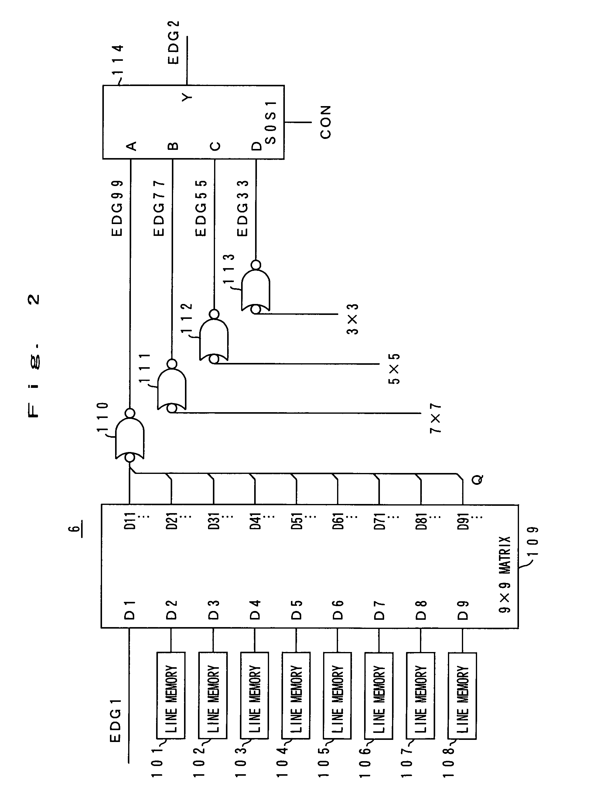
[0066]In FIG. 9, the area color detection portion 21 detects a ratio of monochrome and color for each block area of the input image. The CPU 7 controls the enlarging quantity of the edge area by the edge enlarging portion 6 in accordance with the ratio of monochrome and color. In order to control the edge increasing quantity, an appropriate edge increasing quantity is set out of plural edge area increases such as a four pixel edge area increase by 9×9 matrix, a three pixel edge area increase by 7×7 matrix, a two pixel edge area increase by 5×5 matrix and a one pixel edge area increase by 3×3 matrix.

[0067]For example, in a bloc...


PUM


Abstract

An image processing apparatus includes an edge detecting portion for detecting an edge area of an input image signal and a lightness and chroma detecting portion for detecting a low lightness and low chroma area of the input image signal. An image processing such as edge emphasizing is performed for the edge area of black letters or lines decided by the detection signals of the edge detecting portion and the chroma detecting portion. The image processing apparatus further includes an edge enlarging portion 6 for enlarging the edge area detected by the edge detecting portion 4 and circuits 12 and 19 for converting color image data C, M and Y and black image data K so that C, M and Y color densities in the enlarged edge area is decreased and a black densities is increased. Thus, supporting a high definition, color drift in the edge portions of the black letters or lines of the color image becomes inconspicuous, so that the reproducing quality is improved.

Description

[0001]This application is based on Japanese Patent Application No. 11443 / 1999 filed on Jan. 20, 1999, No. 62584 / 1999 filed on Mar. 10, 1999, the contents of which are incorporated herein by reference.BACKGROUND OF THE INVENTION[0002]1. Field of the Invention[0003]The present invention relates to an image processing apparatus that is mounted in a color copying machine or other equipment. More specifically, the present invention relates to an image processing apparatus that can improve reproducing quality of black letters or lines in a color image.[0004]2. Description of the Prior Art[0005]In the conventional image processing apparatus, in order to improve a reproducing quality of black letters or lines included in a color image, a portion of the black letters or lines in an original image is determined by area determining process, and an image processing such as edge emphasis is performed in accordance with the determination result. The image processing will be explained below.[0006]...

Claims


Application Information

Patent Timeline
IPC IPC(8): G06K9/00G06T5/00H04N1/58
CPCH04N1/4092G06T5/003G06T5/20G06T7/0085H04N1/58G06T2207/10008G06T2207/20192G06T2207/30176G06T2207/10024G06T7/13G06T5/73
Inventor SAWADA, KENICHI
Owner MINOLTA CO LTD
Learn More