Method and apparatus for manufacturing of a wing spar profile element

a manufacturing method and a technology for wing spars, applied in the field of manufacturing methods of wing spars having profiles, can solve the problems of crinkling of blank materials, extra work, and complex manufacturing of beams made of reinforced resin composites, and achieve the effect of cost-effectiveness

Inactive Publication Date: 2009-01-29
SAAB AB
View PDF11 Cites 6 Cited by
  • Summary
  • Abstract
  • Description
  • Claims
  • Application Information

AI Technical Summary

Benefits of technology

[0028]Thereby the profile element can be cost-effective manufactured, which profile element can be used for an aircraft wing spar, wherein two support elements, such as power plant supports, can be mounted near the wing chord.

Problems solved by technology

It is complex to manufacture a beam made of reinforced resin composite, wherein the fibres must follow the curvature of the beam.
This often involves extra work efforts and the blank material has a tendency to be crinkled.
As such a mill of results in a weakened structure of the wing spar, additional material or reinforcing material has to be added to the wing spar within the area of the cavity.
This involves additional weight to the air craft and further costs regarding the manufacture of the wing spar.

Method used


Image

  • Method and apparatus for manufacturing of a wing spar profile element
  • Method and apparatus for manufacturing of a wing spar profile element
  • Method and apparatus for manufacturing of a wing spar profile element

Examples


Embodiment Construction

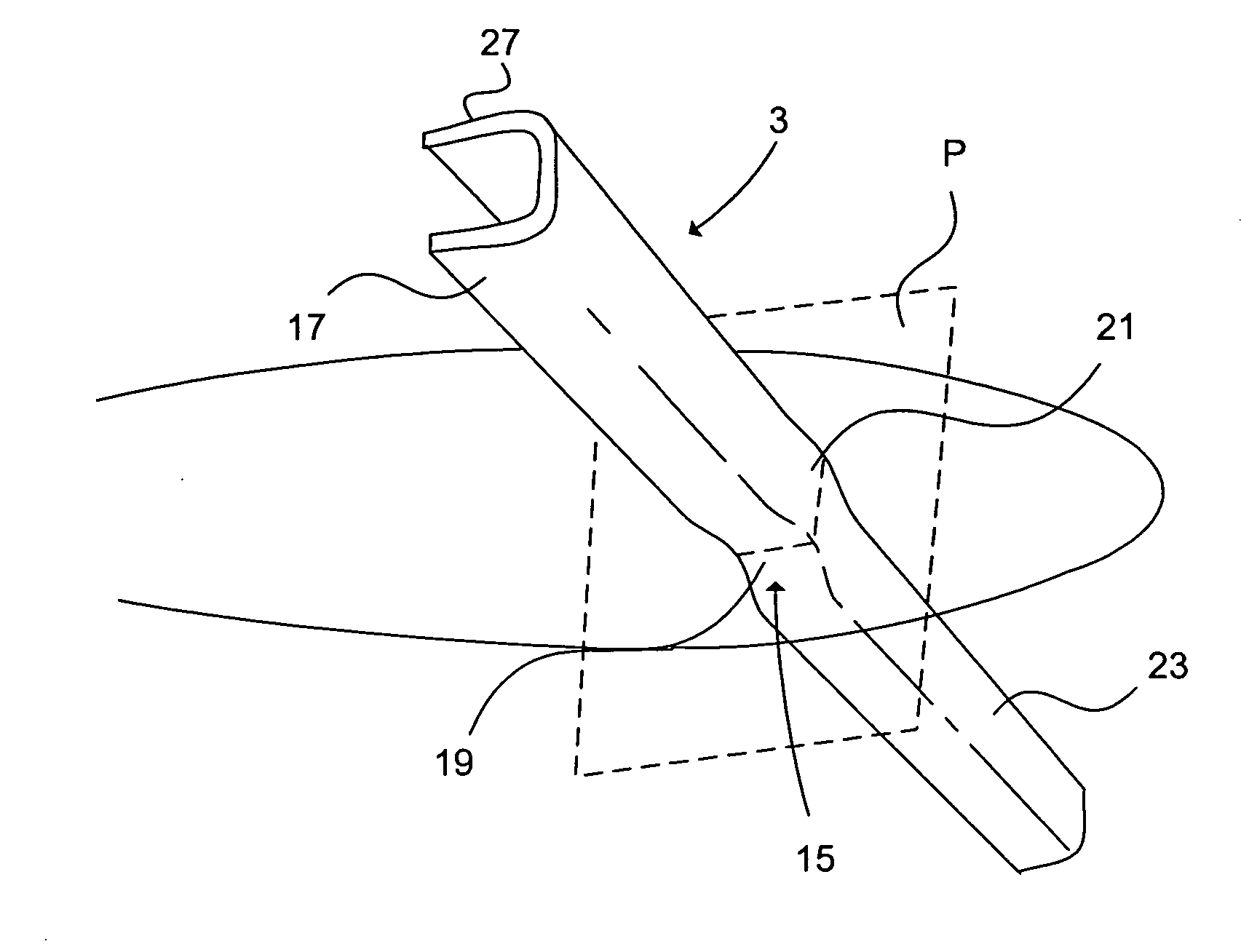
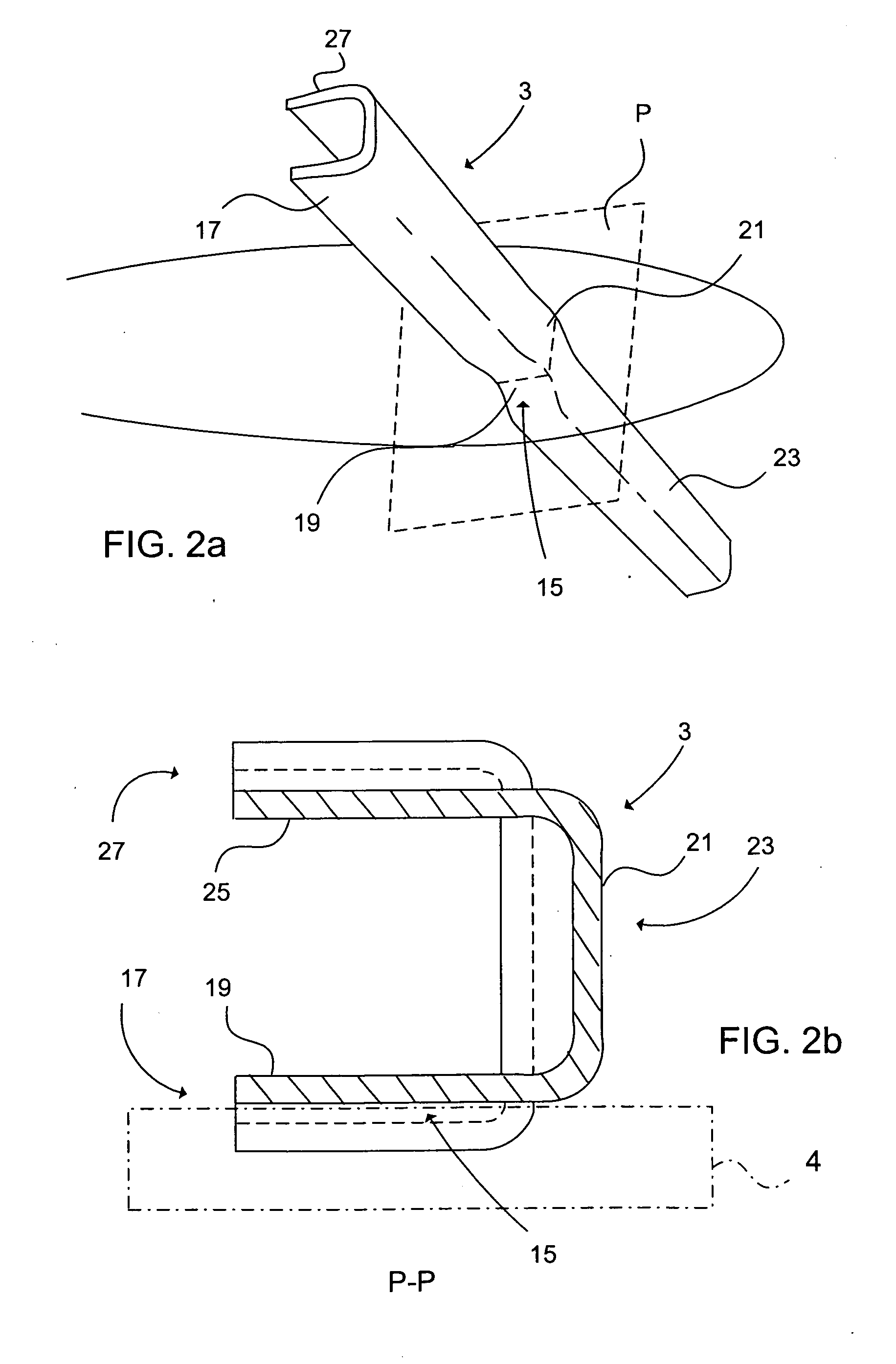
[0038]Hereinafter, embodiments of the present invention will be described in detail with reference to the accompanying drawings, wherein for the sake of clarity and understanding of the invention some details of no importance are deleted from the drawings.

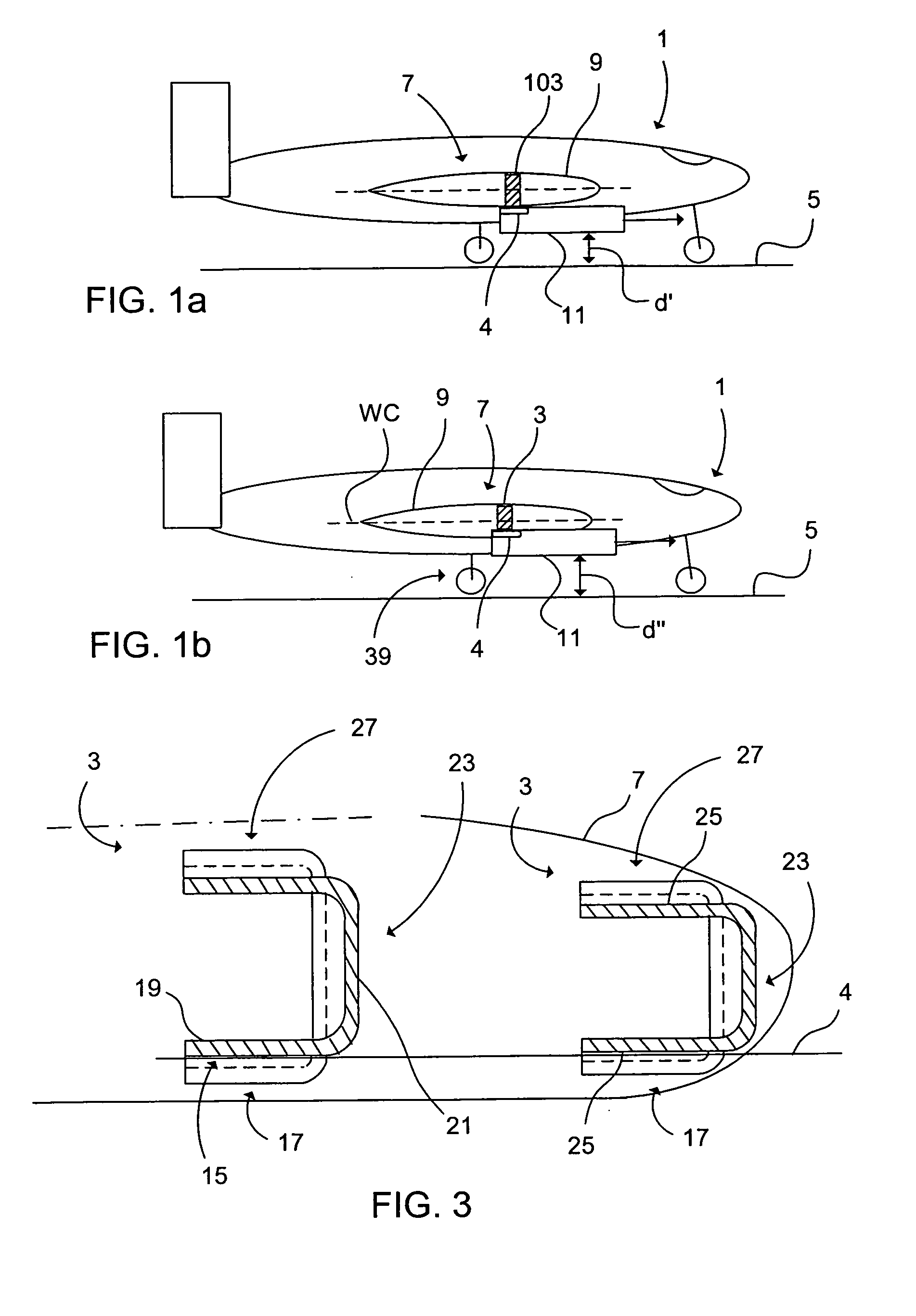
[0039]FIG. 1a illustrates an aircraft 1 without any recesses in its wing spar 103, thereby not accommodating power plant support elements 4. The aircraft 1 is located on the ground surface 5 before take-off. The aircraft's wing 7 comprises the wing spar 103 embodied within the wing shell 9. The aircraft 1 comprises two power plants 11 (only one is shown) located below the wing 7, each power plant 11 is connected to the wing 7 via the power plant support element 4. The distance between ground surface 5 and the power plant 11 is marked with d′. Furthermore, prior art wing spars (not shown) are provided with cavities or recesses, achieved by machining the wingspar (by milling of composite material of the wing spar's lower flange or we...


PUM

PropertyMeasurementUnit
areaaaaaaaaaaa
elongationaaaaaaaaaa
curvatureaaaaaaaaaa

Abstract

A method and an apparatus for manufacture of an elongated beam profile element including a recess configured to accommodate a support element. The method includes forming the blank into the web portion with at least one first protrusion formed to extend across the web portion and to protrude outward from the web portion's outer surface; and into the first flange portion with at least one second protrusion formed to extend across the first flange portion and to protrude inward from the first flange portion's inner surface, wherein this second protrusion merges into the first protrusion and constitutes the recess for accommodating the support element under a wing.

Description

CROSS-REFERENCE TO RELATED APPLICATION[0001]This application claims priority to European patent application 07100884.1 filed 22 Jan. 2007.TECHNICAL FIELD OF THE INVENTION[0002]The present invention relates to a method for manufacturing of a wing spar having a profile, such as C-profile, Ω-profile etc, the wing spar being made of a reinforced resin composite, such as thermo setting plastic, epoxi resins, thermoplastics, polyester resins, fibreglass reinforced plastics etc. The present invention also relates to an apparatus for manufacture of the wing spar.BACKGROUND OF THE INVENTION[0003]It is complex to manufacture a beam made of reinforced resin composite, wherein the fibres must follow the curvature of the beam. Especially when manufacturing C-beams, a common method is to, as a first step, apply “prepreg” material (layers of fibre material previously impregnated with resin, such as thermosetting resin) onto a web forming tool surface and thereafter forming the flanges about flange...

Claims


Application Information

Patent Timeline
Patent Type & Authority Applications(United States)
IPC IPC(8): B29C63/22B29D99/00
CPCB29C70/342B29C70/38Y10T156/1007B29L2031/3085B29C70/386B29D99/0007
Inventor WEIDMANN, BJORNVAARA, JANPETERSSON, MIKAELKROGAGER, MAX
Owner SAAB AB
Why Eureka
Try Eureka