

Method For Braking A Running Metal Strip And Unit For Carrying Out The Method
a technology of running metal strips and braking units, which is applied in the direction of stopper details, cameras, projectors, etc., can solve the problems of increasing wear, not preventing the surface, and not applying sufficient braking action of current brakes, so as to achieve the effect of simple design
- Summary
- Abstract
- Description
- Claims
- Application Information
AI Technical Summary
Benefits of technology
Problems solved by technology
Method used
Image

Examples
Embodiment Construction
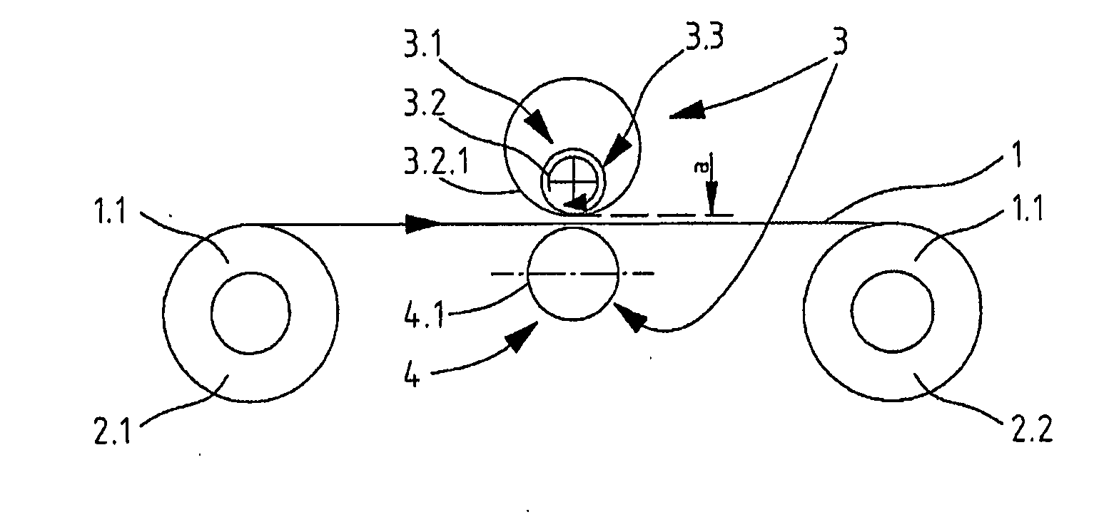
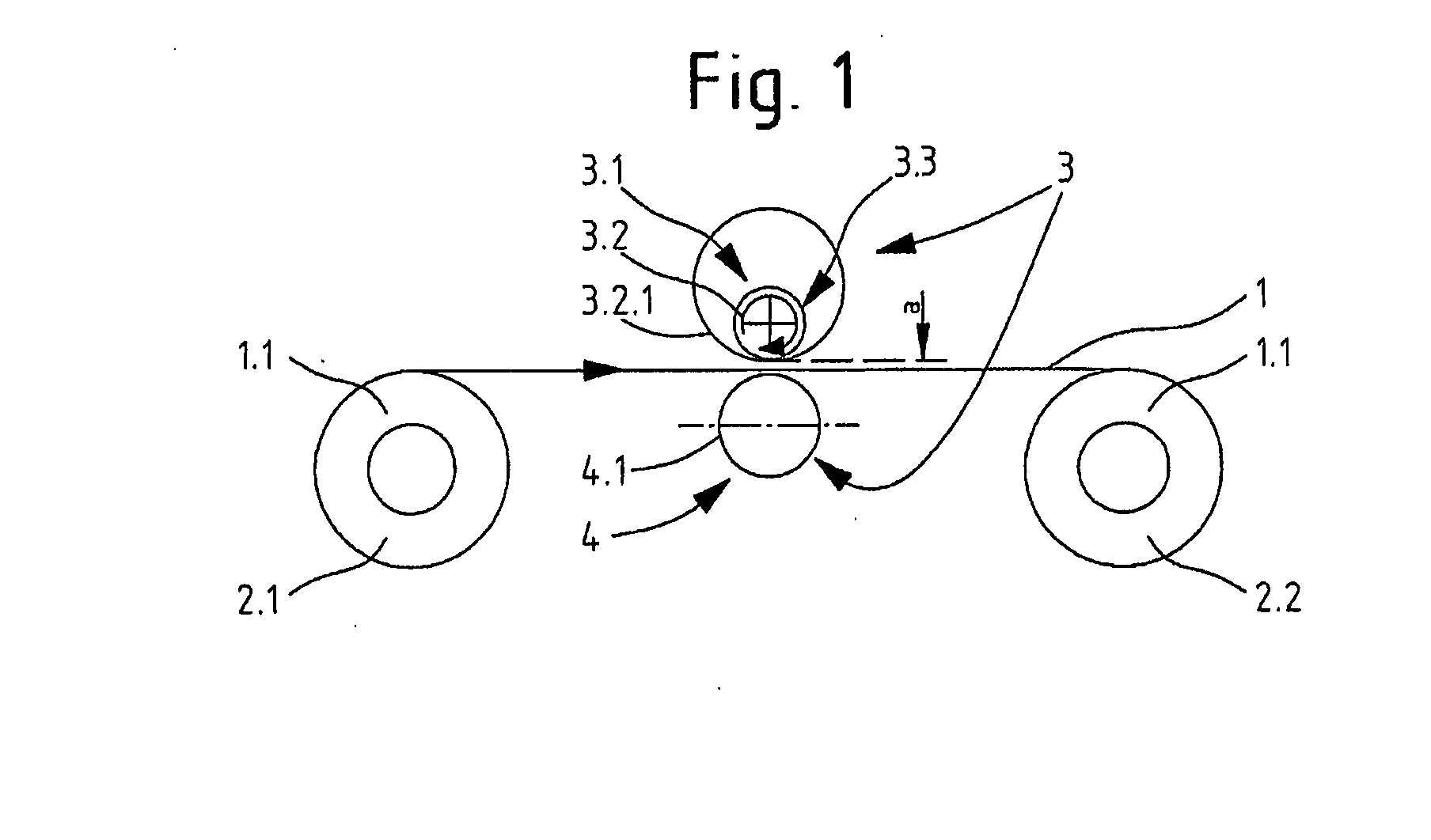
[0043]FIG. 1 schematically shows a unit for lengthwise division (without illustrating the severing devices, such as circular blade cutters, which may be required), in which a metal strip 1 runs from an unwinding reel 2.1 which holds a coil 1.1 onto a winding-up reel 2.2.
[0044]In order to brake the metal strip 1, a braking assembly 3 is provided as an eddy-current brake 3.1 which uses a rotating magnet system 3.2 whose speed can be set and which is arranged above the metal strip 1 on one side in a contactless fashion. A counter-torque which is able to deploy the fully required braking force on its own is now generated in the running metal strip 1 by the rotating magnet system 3.2 as a result of the current induced by the magnetic field.
[0045]A prerequisite for this is that an abutment 4 for counteracting the deviation or ensuring a (contactless) distance a of the metal strip 1 in relation to the rotating magnet system 3.2 is provided beneath the metal strip 1. According to FIG. 1, th...
PUM
| Property | Measurement | Unit |
|---|---|---|
| Thickness | aaaaa | aaaaa |
| Force | aaaaa | aaaaa |
| Centrifugal force | aaaaa | aaaaa |
Abstract
Description
Claims
Application Information