Link for connecting track shoe of crawler belt, assembly for crawler belt, and crawler belt
a technology for crawler belts and crawler belts, which is applied in mechanical equipment, transportation and packaging, and gearing. it can solve the problems of concentrated stress on the adjacent portion of the link, etc., and achieves the effect of preventing damage to increasing the rigidity of the track shoe connecting link, and preventing stress concentration on a specific portion
- Summary
- Abstract
- Description
- Claims
- Application Information
AI Technical Summary
Benefits of technology
Problems solved by technology
Method used
Image
Examples
first embodiment
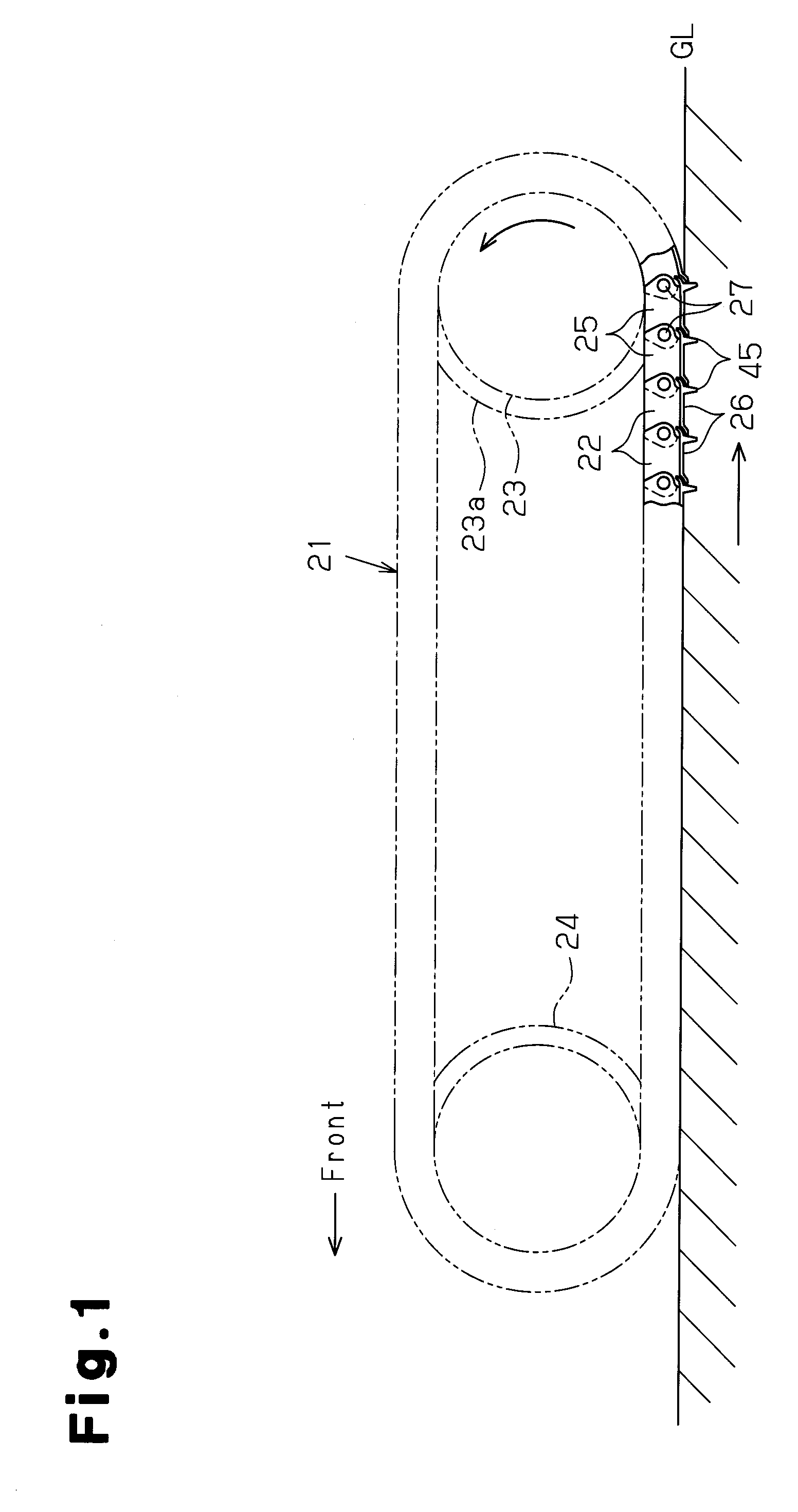
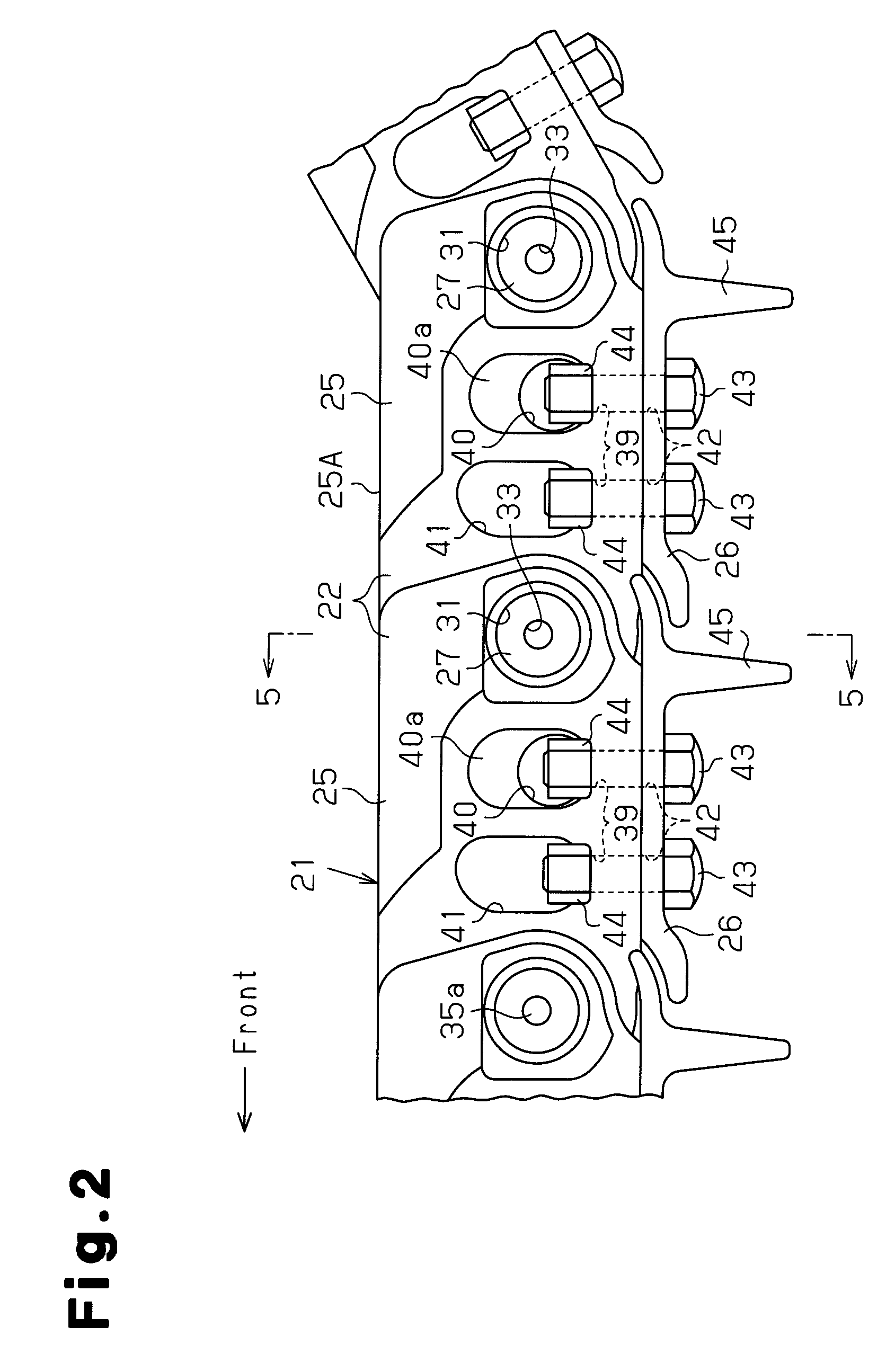
[0038]A first embodiment of the present invention will now be described with reference to FIGS. 1 to 6. In the description of a track shoe connecting link according to the present invention, a front side and rear side are defined as shown in FIGS. 1 and 2.
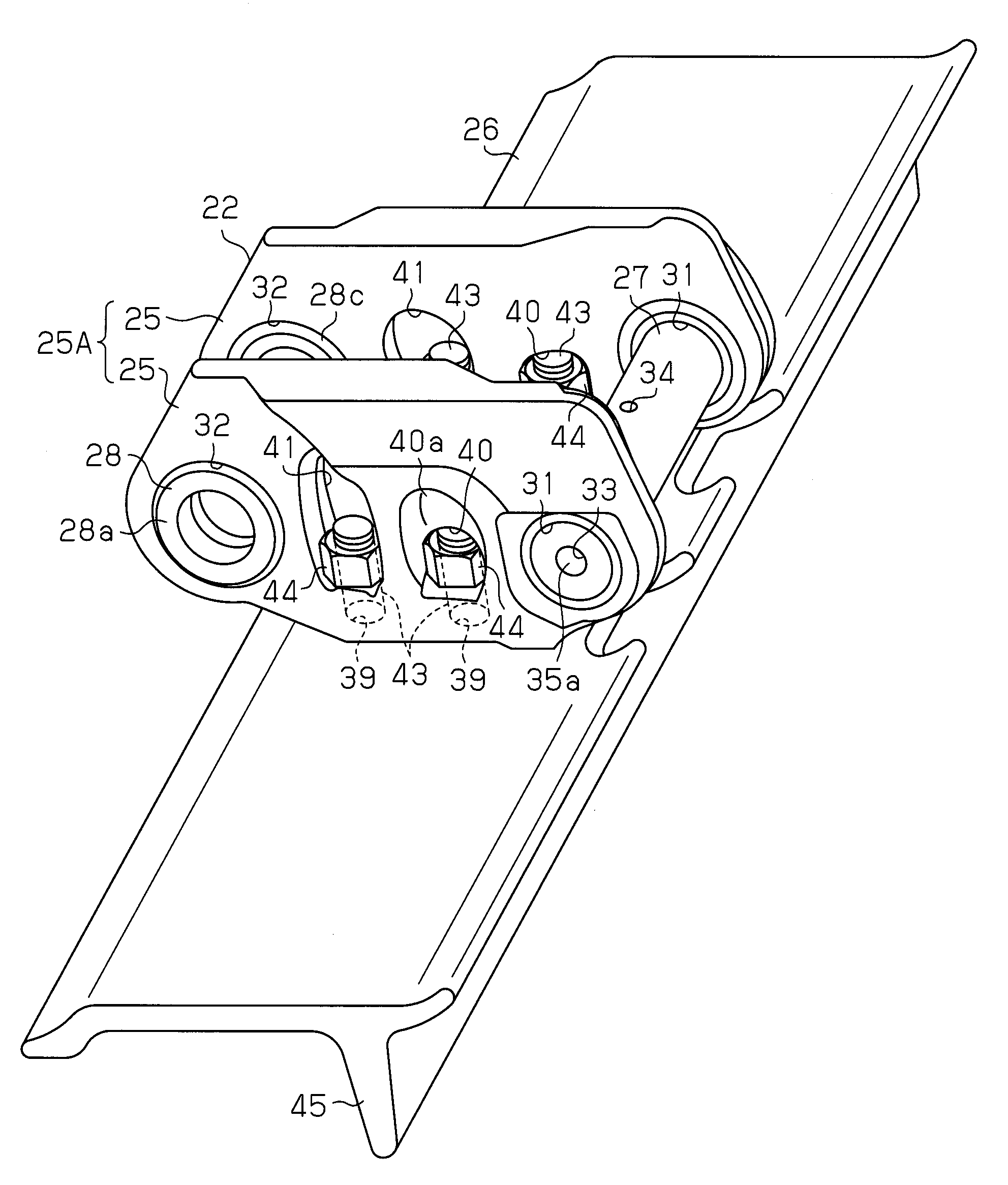
[0039]As shown in FIG. 1, a crawler belt 21 is formed by connecting a plurality of assemblies 22 for a crawler belt in a loop. The crawler belt 21 is wound around a drive wheel 23 and an idler wheel 24 that are respectively arranged at a rear side and a front side in a body frame of a crawler-type work machine such as a bulldozer or a hydraulic excavator with a predetermined distance therebetween. In this state, each of the crawler belt assemblies 22 is meshed with sprocket teeth 23A of the drive wheel 23. Each of the crawler belt assemblies 22 moves around an outer surface of the drive wheel 23 and the idler wheel 24. A plurality of carrier rollers and track rollers (not shown) are supported by the body frame between the drive whe...
second embodiment
[0054]Next, a second embodiment of the present invention will now be described. The differences from the first embodiment will mainly be discussed.
[0055]As shown in FIG. 7, a window hole 48 that functions as an accommodation space is formed at a center of the track shoe connecting link 25, or in a portion that corresponds to the insertion holes 39. The height of the window hole 48 is set so as to increase toward the second shaft hole 32 from the first shaft hole 31. A thin reinforcing wall 48a is formed at an upper end portion of the window hole 48 that is adjacent to the first shaft hole 31. The shape of the window hole 48 makes the rigidity of the track shoe connecting link 25 to become smaller toward the second shaft hole 32 from the first shaft hole 31.
[0056]Therefore, according to the second embodiment, the following advantage is obtained in addition to the advantages obtained in the first embodiment.
[0057](4) The window hole 48 is formed so as to correspond to the insertion ho...
third embodiment
[0058]Next, a third embodiment will now be described. The differences from the first embodiment will mainly be discussed.
[0059]As shown in FIG. 8, the track shoe 26 is fixed to the connecting link pair 25A such that the grouser 45 is adjacent to the second shaft holes 32 of the track shoe connecting links 25. In other words, in the third embodiment, the connecting link pair 25A is provided up-side-down with respect to that of the first and second embodiments. The grouser 45 that faces a front direction or the moving direction of the crawler belt 21 is provided so as to correspond to the sleeves 28 that are adjacent to the open side of the connecting link pair 25A.
[0060]Accordingly, the third embodiment has the following advantage in addition to the advantages obtained in the first embodiment.
[0061](5) Even if the open portion of the crawler belt assembly 22 having the three-side structure faces the front direction of the crawler belt 21, the grouser 45 reinforces the strength of the...
PUM
| Property | Measurement | Unit |
|---|---|---|
| Diameter | aaaaa | aaaaa |
| Height | aaaaa | aaaaa |
| Stiffness | aaaaa | aaaaa |
Abstract
Description
Claims
Application Information
 - R&D
- Intellectual Property
- Life Sciences
- Materials
- Tech Scout
- Unparalleled Data Quality
- Higher Quality Content
- 60% Fewer Hallucinations
Browse by: Latest US Patents, China's latest patents, Technical Efficacy Thesaurus, Application Domain, Technology Topic, Popular Technical Reports.
© 2025 PatSnap. All rights reserved.Legal|Privacy policy|Modern Slavery Act Transparency Statement|Sitemap|About US| Contact US: help@patsnap.com


