Tint Block Image Generation Program, Tint Block Image Generation Device, and Tint Block Image Generation Method

a technology of image generation and tint block, which is applied in the direction of instruments, digital computers, computing, etc., can solve the problems of high concealment capability of latent image in the original and high identification capability of latent image in the copy, and cannot be implemented, so as to maintain the concealment increase the identification capability of latent image in the copy, and increase the output density

Active Publication Date: 2009-01-29
SEIKO EPSON CORP
View PDF5 Cites 13 Cited by
  • Summary
  • Abstract
  • Description
  • Claims
  • Application Information

AI Technical Summary

Benefits of technology

[0028]With the foregoing in view, it is an object of the present invention to provide a method and device to generate tint block images to be printed on an original, which can incr

Problems solved by technology

However, if the latent image portion of the tint block is formed by dots with low screen ruling using a clustered dot screen and the background portion is formed by dots with high screen ruling using a dispersed dot screen, as in the case of prior art, a high concealment capability for the latent image in the original and a high identification capability for the latent

Method used


Image

  • Tint Block Image Generation Program, Tint Block Image Generation Device, and Tint Block Image Generation Method
  • Tint Block Image Generation Program, Tint Block Image Generation Device, and Tint Block Image Generation Method
  • Tint Block Image Generation Program, Tint Block Image Generation Device, and Tint Block Image Generation Method

Examples


examples

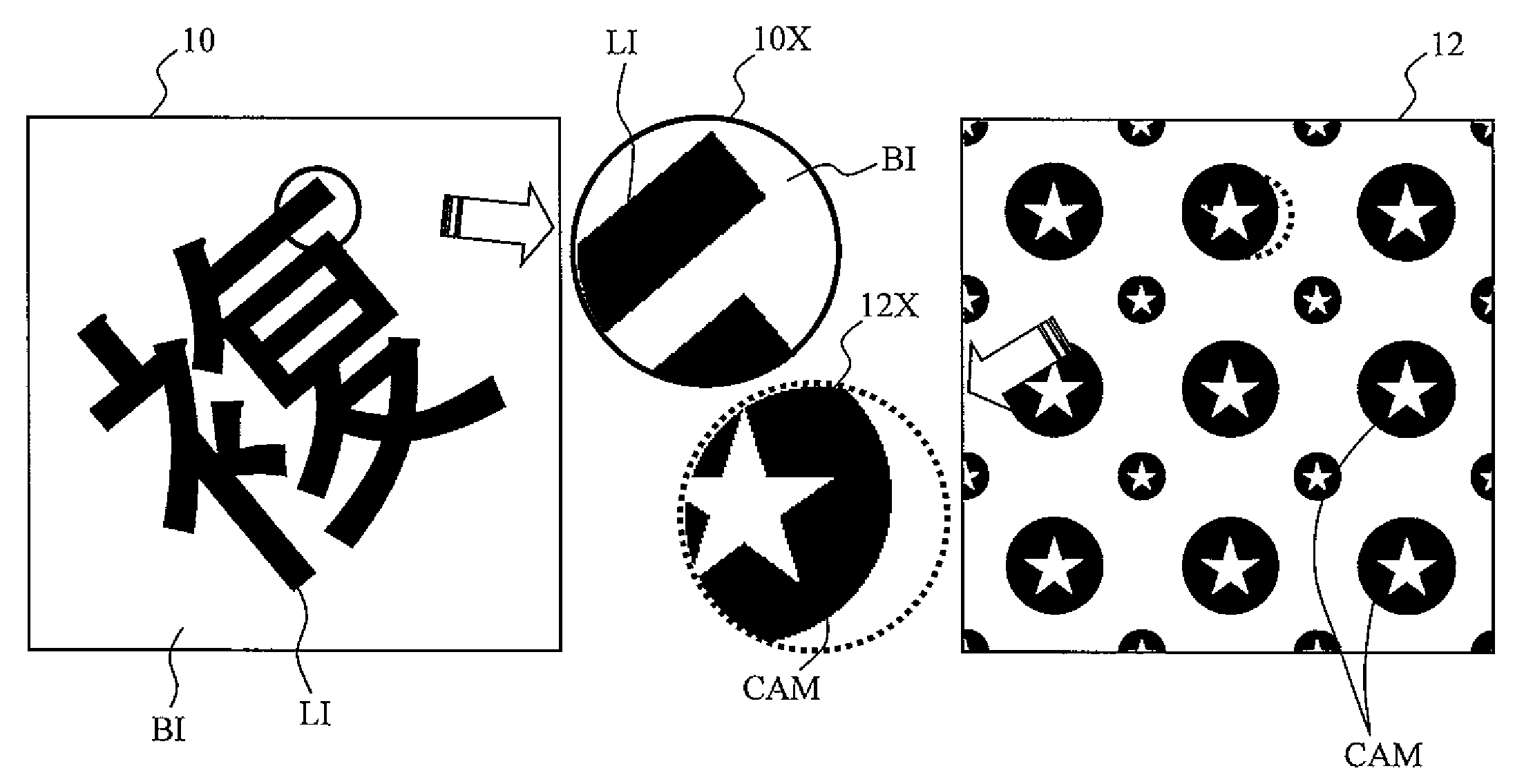
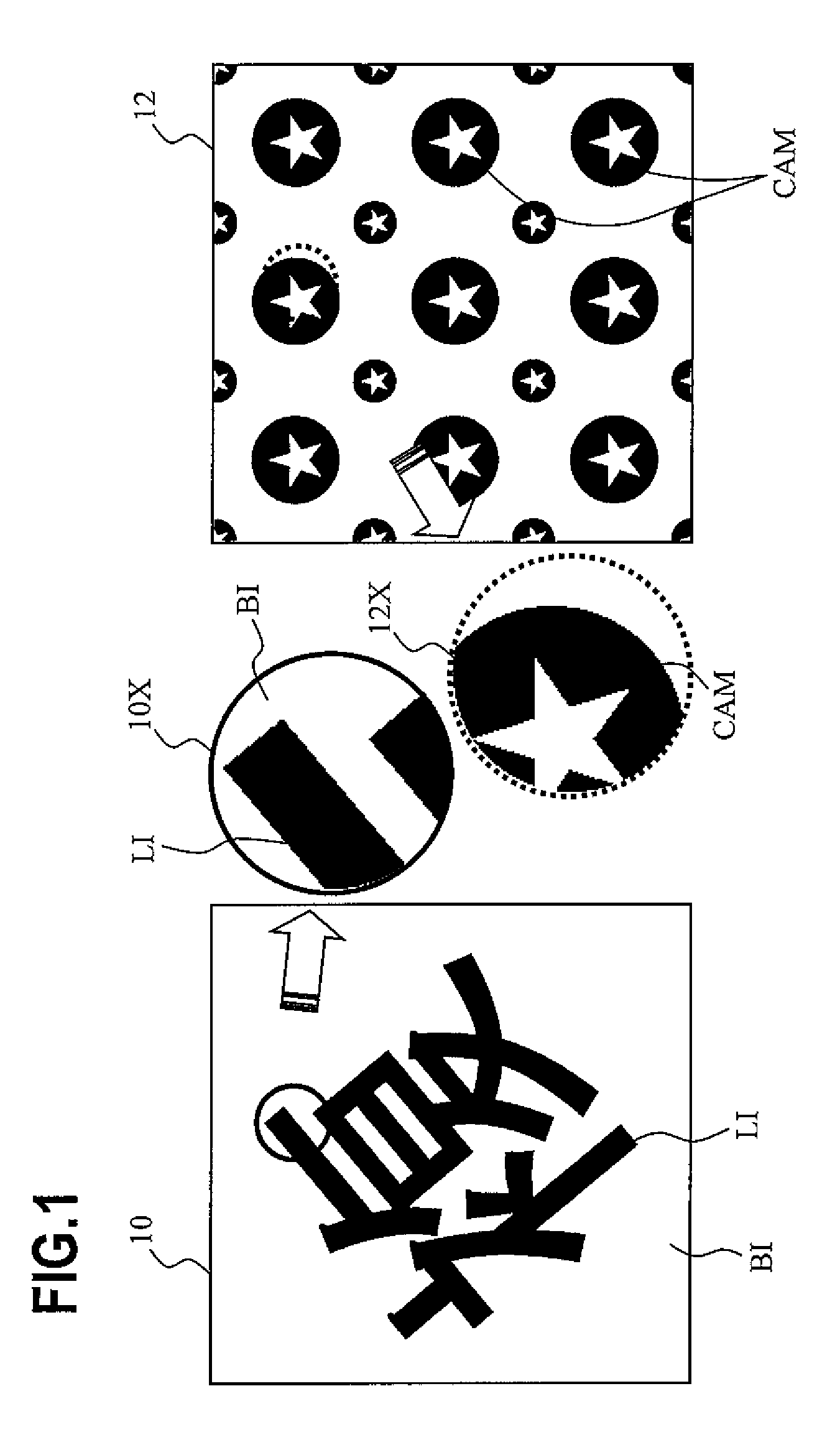
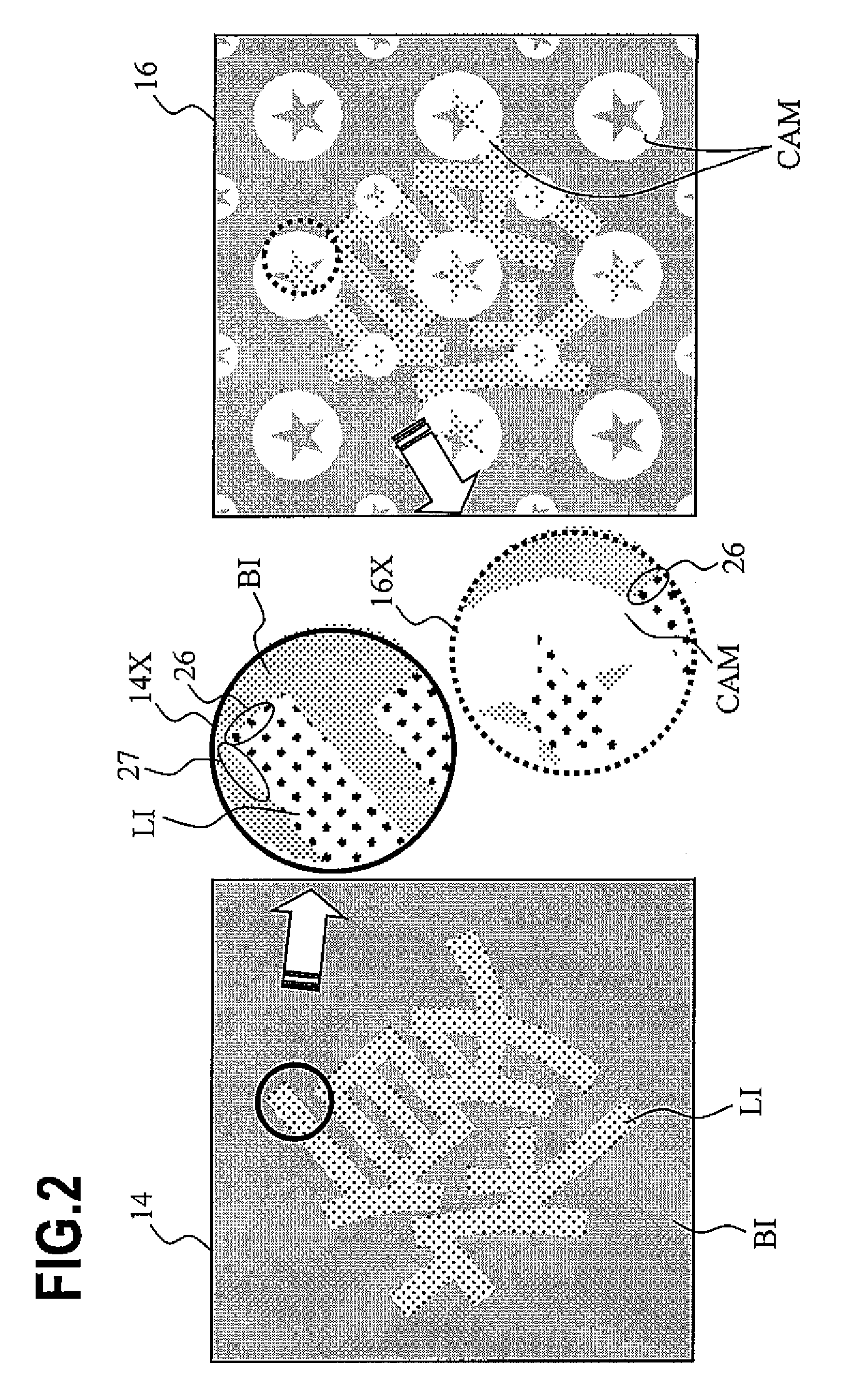
[0124]The following are examples when the tint block image is generated using a pair of the latent image portion dither matrices 33-1, 33-2 or 33-3 and the background portion dither matrices 34-1, 34-2 or 34-3 shown in FIG. 7, FIG. 8 or FIG. 9, and the tint block image of the copy is generated by simulation to allow the pixel dots of the tint block image of the original to disappear at a predetermined ratio. In simulation, the image reproducing capability, which depends on the input resolution and the output resolution of copying, has a limitation, so a size of large dots (half tone dots) is decreased to a first ratio, and a size of small dots (half tone dots) is decreased to a ratio smaller than the first ratio, and micro dots (pixel dots) are allowed to disappear at a predetermined ratio.

[0125]FIG. 16 shows an original and a copy of the tint block image of the example. FIG. 17 is an enlarged view of the original and the copy of the tint block image. In FIG. 16 and FIG. 17, the bac...


PUM


Abstract

A computer readable storage medium stores a tint block image generation program for generating tint block image data for forming, on a print medium, a tint block image including a latent image portion which is reproduced by copying, and a background portion of which copy output density drops. The program has a latent image portion generation step of generating data of a plurality of first dots in the latent image portion based on a dot clustered screen; and a background portion generation step of generating data of a plurality of second dots and data of a plurality of third dots dispersed among the second dots and having a size smaller than the second dots. And the first dots in the latent image portion and the second dots in the background portion are arranged at positions on common displacement vectors in an area of the tint block image.

Description

CROSS-REFERENCE TO RELATED APPLICATIONS[0001]This application is based upon and claims the benefit of priority from the prior Japanese Patent Applications No. 2007-160365, filed on Jun. 18, 2007, and No. 2008-128241, filed on May 15, 2008, the entire contents of which are incorporated herein by reference.BACKGROUND OF THE INVENTION[0002]1. Field of the Invention[0003]The present invention relates to a tint block image generation program, a tint block image generation device, and a tint block image generation method, and more particularly to a program and device for generating tint block image data for printing a tint block image on a print medium. The present invention also relates to a tint block image generation program and generation device, and tint block image generation method, having an effect to inhibit forgery by copying a print medium (original) on which a tint block image is printed based on the tint block image data, or an effect to distinguish between the original and t...

Claims


Application Information

Patent Timeline
IPC IPC(8): G06F15/00
CPCH04N1/00864H04N1/4055H04N1/00883H04N1/0087
Inventor KOBAYASHI, MAKOTO
Owner SEIKO EPSON CORP
Why Eureka
Try Eureka