Split bearing

a technology of split bearings and bearings, applied in the direction of needle bearings, shafts and bearings, bearings, etc., can solve the problems of difficult to incorporate the integration mechanism of forming grooves or the like in this thin outer ring, and the integral type of bearings cannot be used, so as to achieve the effect of reducing the thickness of the split bearing in the radial direction, easy clamping, and smooth elastic deformation of the hook-shaped portion

Inactive Publication Date: 2009-01-29
JTEKT CORP
View PDF0 Cites 14 Cited by
  • Summary
  • Abstract
  • Description
  • Claims
  • Application Information

AI Technical Summary

Benefits of technology

[0011]Further, the problem to be solved by the invention is to provide means for enabling integrating work to be easily conducted by only one worker, when an outer ring which is divided in two is assembled, by rendering the outer ring to be automatically held with respect to a radial direction by the cage which has been mounted to a shaft to which the cage is to be mounted, so as not to be detached, even in case where a rolling bearing is employed as a split bearing.
[0032]According to the invention, the integrating mechanism of the split bearing is provided on the rib of the outer ring. Therefore, even in case where the rolling bearing is employed as the split bearing, the integrating mechanism can be easily and reliably incorporated, without badly affecting the rolling performance of the rolling bearing itself, and the split bearing can be preassembled to the bearing part so as not to be detached.
[0033]Then, according to the invention, because the integrating mechanism of the split bearing are provided on the side surface of the rib, the outer peripheral surface of the outer ring can be made flush, and the outer ring can be accurately incorporated in to the bearing part. Moreover, the integrating mechanism is highly reliable, because the integrating mechanism has a simple structure including the concave groove and the connecting member such as the C-shaped ring.
[0034]Then, according to the invention, because the concave groove for providing the integrating mechanism is formed on the outer peripheral surface of the outer ring, the work can be easily conducted. Moreover, because the concave groove of the integrating mechanism is formed on the outer peripheral surface partially in the circumferential direction, only a smaller amount of the work is required.
[0037]According to the invention, when the outer ring is moved from outside to inside in the radial direction to be assembled to the hook-shaped portion, elastic deformation of the hook-shaped portion is smoothly performed, and the outer ring can be easily clamped by the hook-shaped portion. As the results, the assembling work of the outer ring can be more easily performed by one worker.
[0038]According to the invention, the thickness of the split bearing in the radial direction can be reduced, whereby a compact structure can be realized.

Problems solved by technology

A bearing of an integral type cannot be employed for a crank journal of this crankshaft or a bearing part at a large end of a con-rod, because of the particular crank shape of the crankshaft.
Therefore, there is such a problem that it is very difficult to provide the conventional integrating mechanism on the outer ring.
Accordingly, the width of the thickness for forming the outer ring is inevitably made smaller than the width of the thickness of the conventional slide bearing, and so, it is difficult to incorporate the integrating mechanism of forming a groove or the like in this thin outer ring.
Even though the integrating mechanism has been incorporated, there is such anxiety that rolling performance would be badly affected.
Therefore, in case where this rolling bearing having a large number of components is integrated by the conventional integrating mechanism as described above, there is such inconvenience that the integrating work is considerably annoying.
There is such inconvenience that this integrating work is considerably annoying.

Method used


Image

  • Split bearing
  • Split bearing
  • Split bearing

Examples


first embodiment

[0052]Now, an embodiment according to the invention will be described referring to the drawings. A split bearing in this embodiment is a rolling bearing of a needle roller bearing type, particularly in case where it is applied to a crank journal of a crankshaft and a bearing part at a large end of a con-rod in an internal combustion engine (engine).

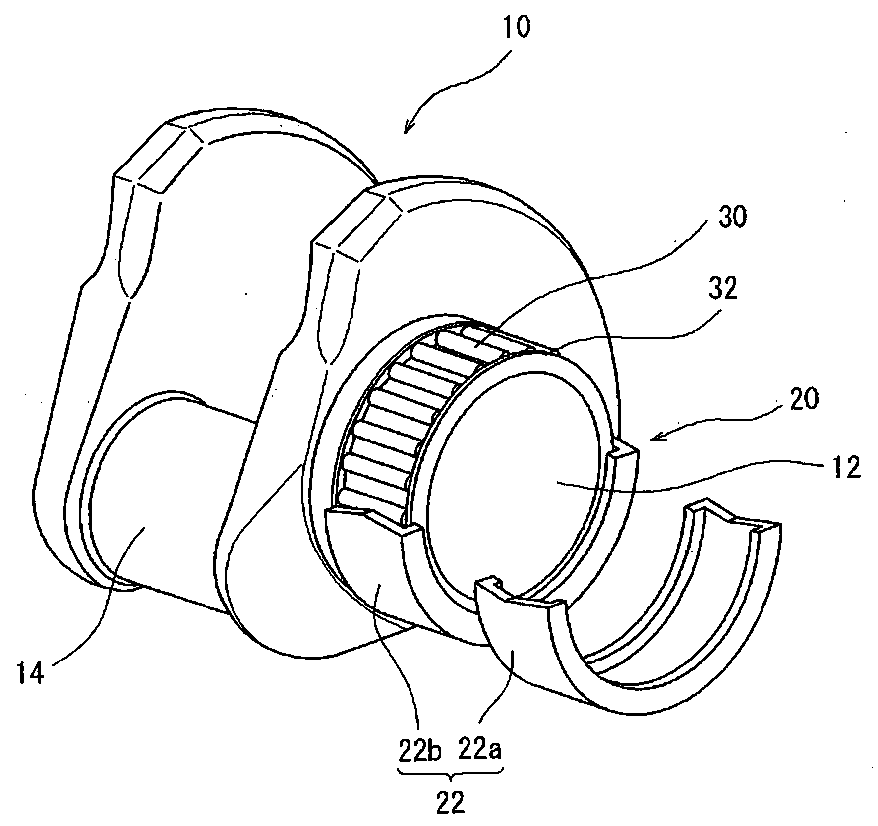
[0053]FIG. 1 is a perspective view showing apart of an ordinary crankshaft to be incorporated in an internal combustion engine. As shown in FIG. 1, a crankshaft 10 is formed in a crank shape, as an integral type. A crank journal 12 of this crankshaft 10 is pivotally held by a body part of the internal combustion engine (not shown) by way of a rolling bearing 20. As the rolling bearing 20, a rolling bearing of an integral type in a ring-like shape cannot be employed due to a particular shape of the crankshaft 10 which is integrally formed in a crank shape, and so, a split bearing which is divided in two in a circumferential direction is em...

second embodiment

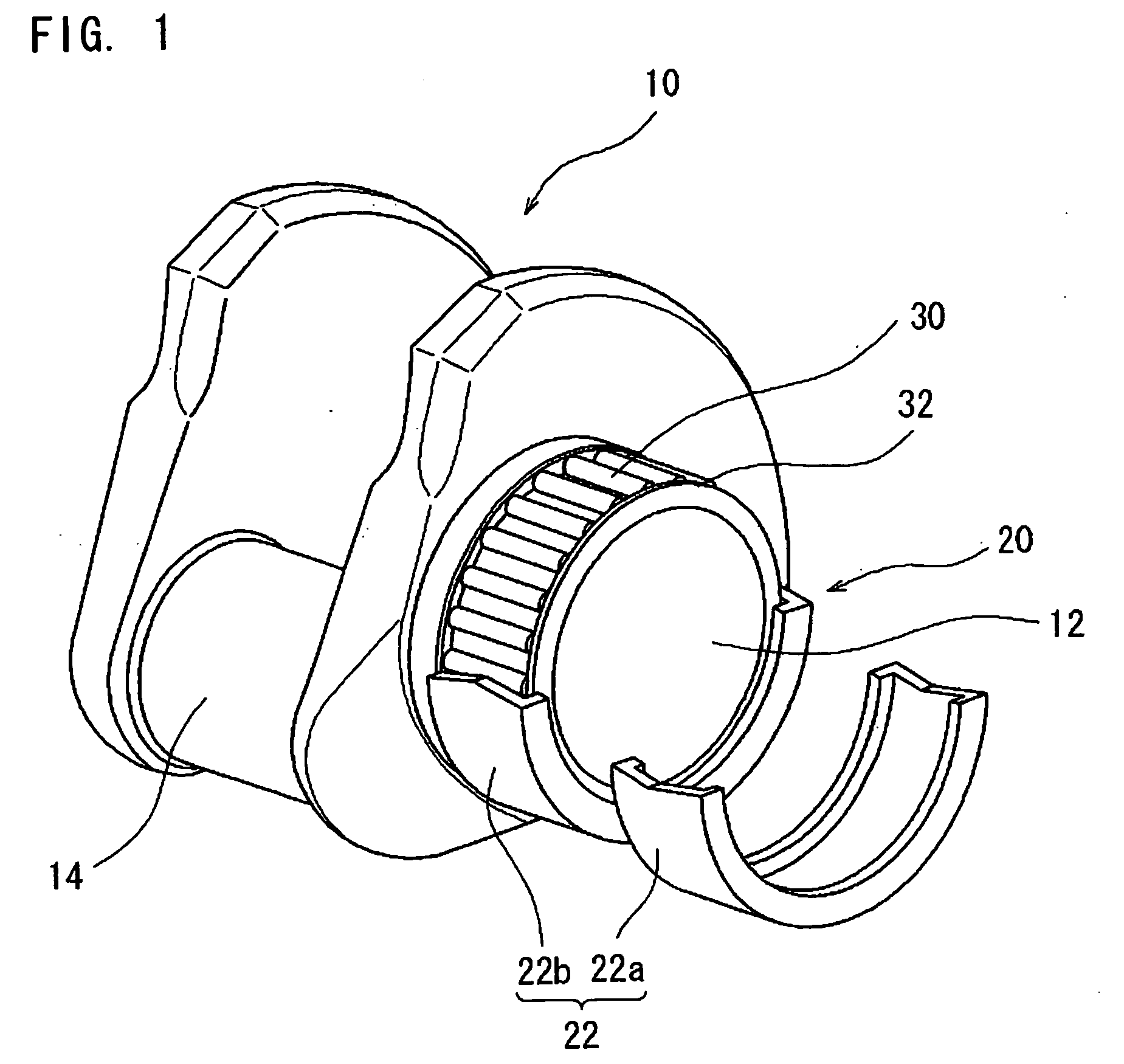
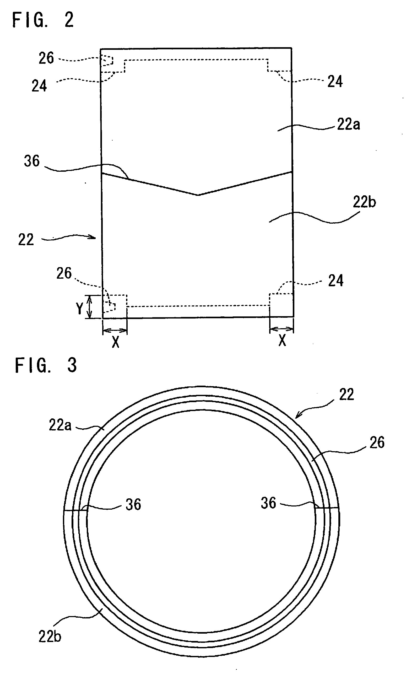
[0070]Then, the integrating mechanism for integrating the split bearing in a second embodiment will be described. FIGS. 5 to 7 show the integrating mechanism in the second embodiment. FIGS. 5 and 6 show the outer ring 22, wherein FIG. 5 is a front view, and FIG. 6 is a side view. FIG. 7 is a perspective view of a split tube 29 as the connecting member. It is to be noted that the same constituting parts as in the above described first embodiment will be denoted with the same reference numerals and detailed description of the same will be omitted.

[0071]As well shown in FIG. 5, the integrating mechanism in the second embodiment includes concave grooves 27 which are formed on the outer peripheral surfaces of the ribs 24 at the both sides of the outer ring 22 by cutting away in a rectilinear shape. These concave grooves 27 are formed on a part of the outer peripheral surface in the circumferential direction so as to go across the dividing plane 36 in a V-shape between the upper outer rin...

third embodiment

[0079]Next, a third embodiment of the present invention will be described with reference to FIGS. 8 through 10. In the third embodiment of the invention, those portions similar in construction to the corresponding portions of the first embodiment will be designated by identical reference numerals, respectively, and explanation thereof will be omitted.

[0080]The outer ring 22 which is a constituent member of this rolling bearing 20 is divided in two so that it can be mounted to the shaft to which the outer ring is to be mounted, such as the crank journal 12, from outside in the radial direction. Moreover, the cage 32 for holding the needle rollers 30 is in a dual ended cylindrical shape which is cut out at one position in a circumferential direction. The cage 32 is elastically deformed, and fitted to the shaft to which the cage is to be mounted from the cut-out position so as not to be detached from the shaft.

[0081]On occasion of incorporating the crankshaft 10 into the body part of t...


PUM


Abstract

A split bearing which is divided in two is formed of a rolling bearing, and its outer ring is provided with ribs at both side parts thereof in an axial direction. An integrating mechanism is provided at a position within a range in the axial direction where this rib is formed. The integrating mechanism include a concave groove in an annular shape which is formed on a side surface of the rib, and a C-shaped ring is engaged with this concave groove, whereby upper and lower split outer ring pieces of the divided outer ring are integrated into a preassembled state.

Description

BACKGROUND OF THE INVENTION[0001]The present invention relates to a split bearing. Particularly, the invention relates to the split bearing which is applied to a crank journal of a crankshaft and a large end of a con-rod or a connecting rod in an internal combustion engine, and specifically, to the split bearing which has an outer ring provided with ribs and, and to the split bearing which has rolling elements provided on an inner peripheral part of an outer ring, and a cage for holding the rolling elements.[0002]A crankshaft in an internal combustion engine which is mounted on a vehicle such as an automobile is usually formed as a crankshaft of an integral type having a crank shape. A bearing of an integral type cannot be employed for a crank journal of this crankshaft or a bearing part at a large end of a con-rod, because of the particular crank shape of the crankshaft. For this reason, a split bearing which has been divided into two portions in a circumferential direction has bee...

Claims


Application Information

Patent Timeline
Patent Type & Authority Applications(United States)
IPC IPC(8): F16C35/00
CPCF16C9/00F16C43/06F16C33/60F16C19/46
Inventor IWATA, TAKASHIWASEDA, YOSHITAKA
Owner JTEKT CORP
Why Eureka
Try Eureka