Clip

a technology of clip and pin, applied in the field of clips, can solve problems such as the danger of losing one, and achieve the effects of reducing the insertion force, small pin insertion force, and large attachment for

Inactive Publication Date: 2009-01-29
NEWFREY
View PDF12 Cites 17 Cited by
  • Summary
  • Abstract
  • Description
  • Claims
  • Application Information

AI Technical Summary

Benefits of technology

[0006]An object of the present invention is to provide a clip comprising a pin and a grommet wherewith, while maintaining a large force of attachment to the member being attached to, the pin insertion force is reduced.
[0008]By the clip described above, a clip comprising a pin and grommet is obtained wherewith the pin insertion force is reduced while maintaining a large force of attachment to the member being attached to.
[0009]The configuration of the clip described above can be effected so that the tip of the inside folded-back portion of the tip portion of the leg piece latches in a permanent fastening latching channel formed in the tip of the pin shaft, and so that the permanent fastening condition with the diameter of the leg expanded is maintained. When that is the case, the length in the axial direction of the leg pieces and the length in the axial direction of the shaft can be selected to lengths wherewith, in the permanent fastening condition described above, the shaft tip and the leg tip are at substantially the same position. As a consequence, even if the length of the clip overall is made short, a small pin insertion force can be maintained while maintaining a large attachment force.
[0010]The pin and the grommet can be configured so as to be coupled in a condition wherein the diameter of the grommet leg is not expanded with the pin shaft inserted into the grommet leg. The configuration can also be made so that, by further inserting the pin shaft into the grommet leg, the tip of the inside folded-back portion of the tip portion of the leg pieces latches in the permanent fastening latching channel formed in the tip of the pin shaft, and the permanent fastening condition with the diameter of the leg expanded is maintained.

Problems solved by technology

For that reason, prior to the fastening operation, time and effort are required to assemble the one part with the other part, and there is a danger of losing one part

Method used


Image

  • Clip
  • Clip
  • Clip

Examples


Embodiment Construction

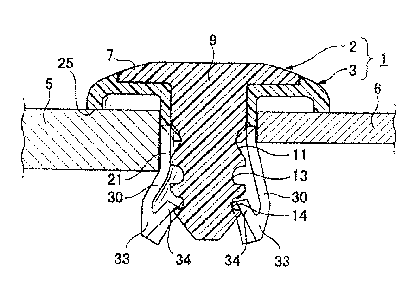
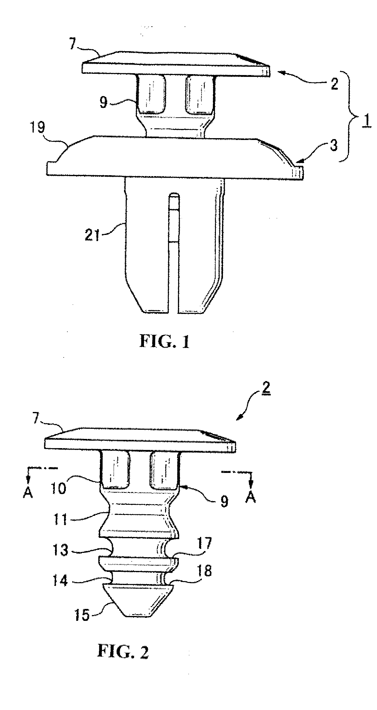
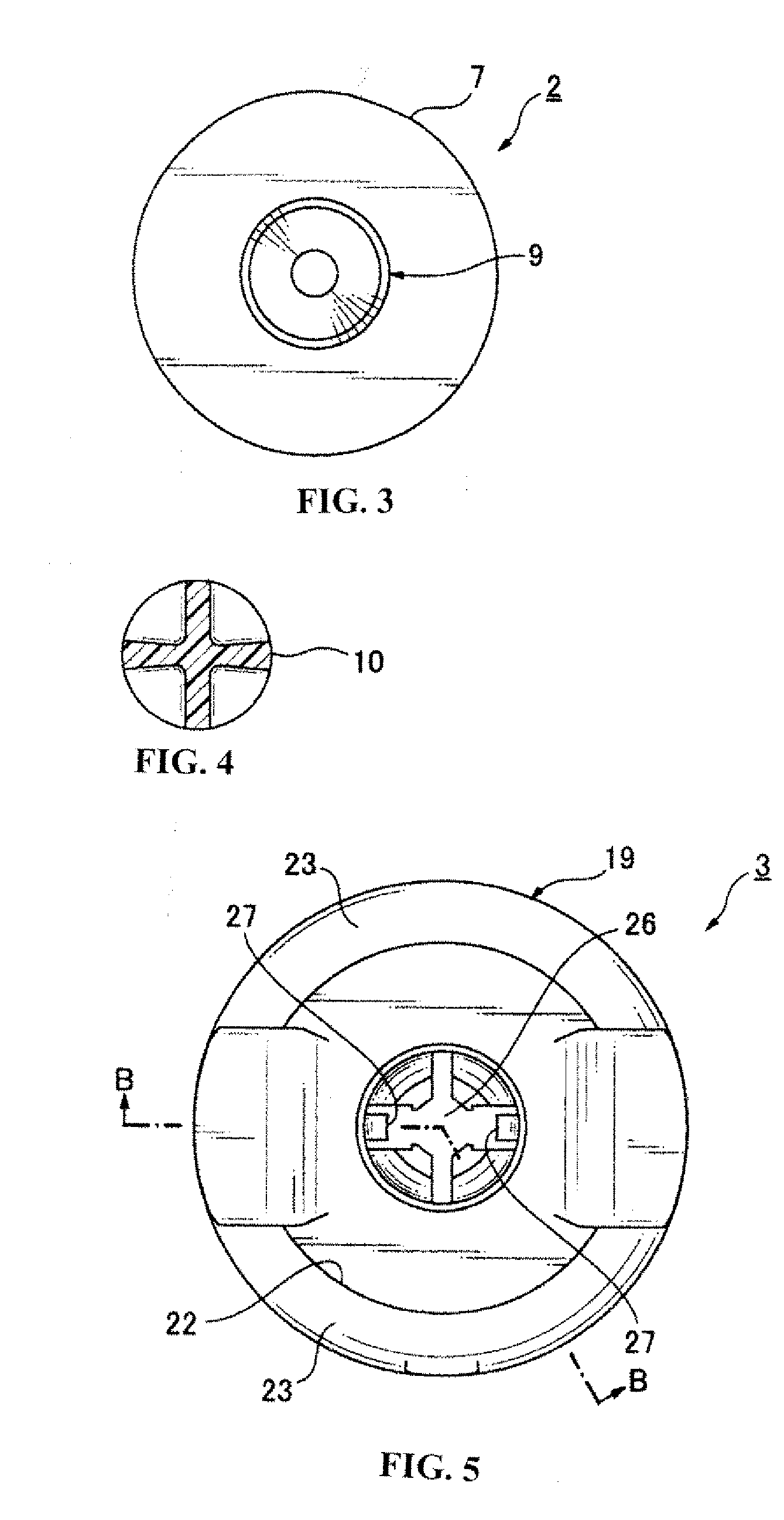
[0023]A clip relating to one exemplary embodiment of the present invention is now described with reference to the drawings. A clip 1, as diagrammed in FIG. 1, is a two-part clip comprising a pin 2 made of a hard plastic, and a grommet 3, made of plastic, to which the pin 2 is coupled. FIGS. 2 to 4 represent the pin 2 by itself while FIGS. 5 to 9 represent the grommet 3 by itself. FIGS. 10 to 12 represent sections of the clip 1 in various conditions wherein the pin 2 and grommet 3 are coupled. FIG. 10 represents, in greater detail, the clip 1 in the as-delivered product condition, prior to use, with the pin 2 coupled to the grommet 3, with the shaft of the pin 2 not expanding the diameter of the grommet leg. By coupling the pin 2 and the grommet 3, in addition to making the management and attachment operation of the two-part clip 1 easy, loss of one or other of the parts, that is, namely the pin 2 or the grommet 3, is prevented. FIG. 11 represents the permanent fastening condition, w...


PUM


Abstract

A clip including a pin and a grommet, a leg is formed by a plurality of narrow leg pieces, the tip portions of the leg pieces have inside folded-back portions that are folded back from the tips toward the inside of the leg and extend toward a flange, a gap is formed between the inside folded-back portions and the outside portions of the tip portions of the leg pieces, and the leg pieces are formed in narrow flexible plate shapes which extend at constant thickness from the root portion adjacent the flange to intermediate positions in the tip portions.

Description

CROSS-REFERENCE TO RELATED APPLICATIONS[0001]This application claims the benefit of Japanese Application No. 2007-194850, filed Jul. 26, 2007. The disclosure of the above application is incorporated herein by reference.BACKGROUND OF THE INVENTION[0002]This invention relates to a clip comprising a pin and a grommet, and, more particularly, to such a clip, the shaft of which pin is inserted into a leg of the grommet, expanding the diameter of the grommet leg, which clip is attached to a panel or other member being attached to, by that expanded-diameter leg and a grommet flange.[0003]Plastic clips comprising a plastic pin and a plastic grommet, the shaft of which pin is inserted into the grommet, expanding the diameter of the grommet leg, which clip is attached to a panel or other member being attached to, by that expanded-diameter leg and a grommet flange, are described, for example, in JIKKAI [Unexamined Utility Model Application] No. S51-134166 / 1976 (Gazette) (Patent Literature 1). ...

Claims


Application Information

Patent Timeline
Patent Type & Authority Applications(United States)
IPC IPC(8): F16B13/06
CPCF16B21/073
Inventor SHIBUYA, TOMIO
Owner NEWFREY
Why Eureka
Try Eureka