Non-contact type tonometer

a tonometer and non-contact technology, applied in the field of tonometers, can solve the problems of large instruments, inability to secure the accuracy of both the applanation and the range needed for xy alignment of the tonometer, and the complexity of the optical system of the tonometer, so as to achieve compact optical systems and relatively simple results

Inactive Publication Date: 2009-01-29
KK TOPCON
View PDF8 Cites 55 Cited by
  • Summary
  • Abstract
  • Description
  • Claims
  • Application Information

AI Technical Summary

Benefits of technology

[0014]The present invention has been made in light of the above-described problems, and an object of the present invention is to provide a non-contact type tonometer which enables simultaneous securement of an intraocular pressure value measurement accuracy with applanation and of the range needed for a Z alignment, while making an optical system compact and relatively simple.

Problems solved by technology

However, since the non-contact type tonometer described in Japanese Patent Application Publication No. 2002-165763 uses the five light sources, which are independently set, the tonometer requires a complex optical system due to the installation of an independent projection system for each light source.
This causes a problem in that the instrument becomes large.
Since a range illuminated by the circular light flux is used for the XY alignment and the applanation detection, this tonometer has a problem in that the tonometer fails to secure both an intraocular pressure value measurement accuracy in the applanation and a range needed for the XY alignment.
More specifically, when the range illuminated by the circular light beam is increased, the range needed for the XY alignment can be increased, but the intraocular pressure value measurement accuracy in the applanation is deteriorated.
In particular, although there is a demand for increasing a range needed for an alignment as large as possible for an auto-alignment tonometer performing an alignment automatically, these conventional tonometers fail to meet such a demand.

Method used


Image

  • Non-contact type tonometer
  • Non-contact type tonometer
  • Non-contact type tonometer

Examples


Embodiment Construction

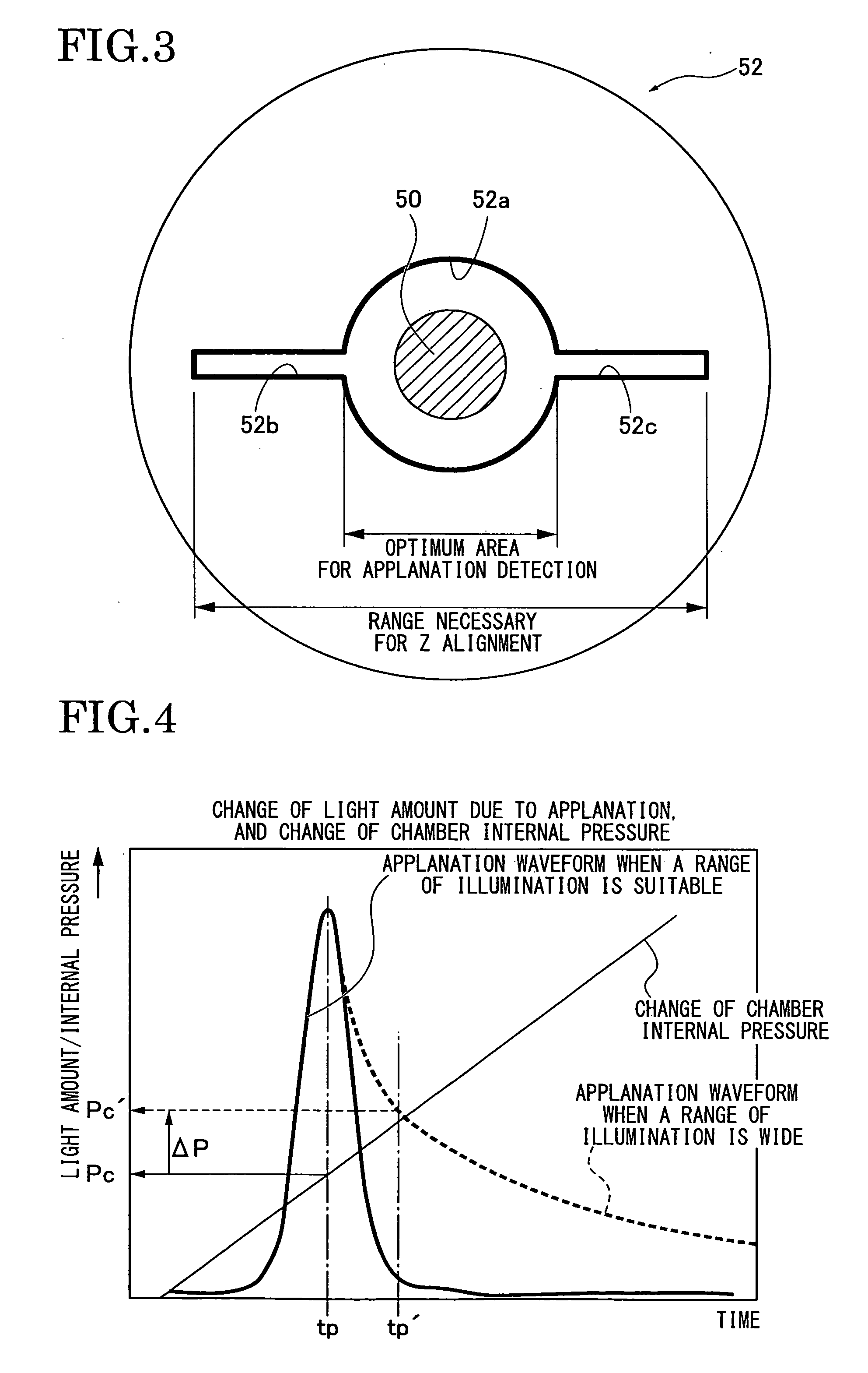
, and the first embodiment when a light amount of a Z alignment light receiving sensor changes due to a movement of the cornea of a subject's eye.

[0023]FIG. 8 is a front view showing Variation 1 of the shape of an aperture.

[0024]FIG. 9 is a front view showing Variation 2 of the shape of an aperture.

DETAILED DESCRIPTION OF THE PREFERRED EMBODIMENTS

[0025]A preferred embodiment for carrying out a non-contact type tonometer of the present invention is described below with reference to a first embodiment shown in the accompanying drawings.

[0026]First, a configuration is described.

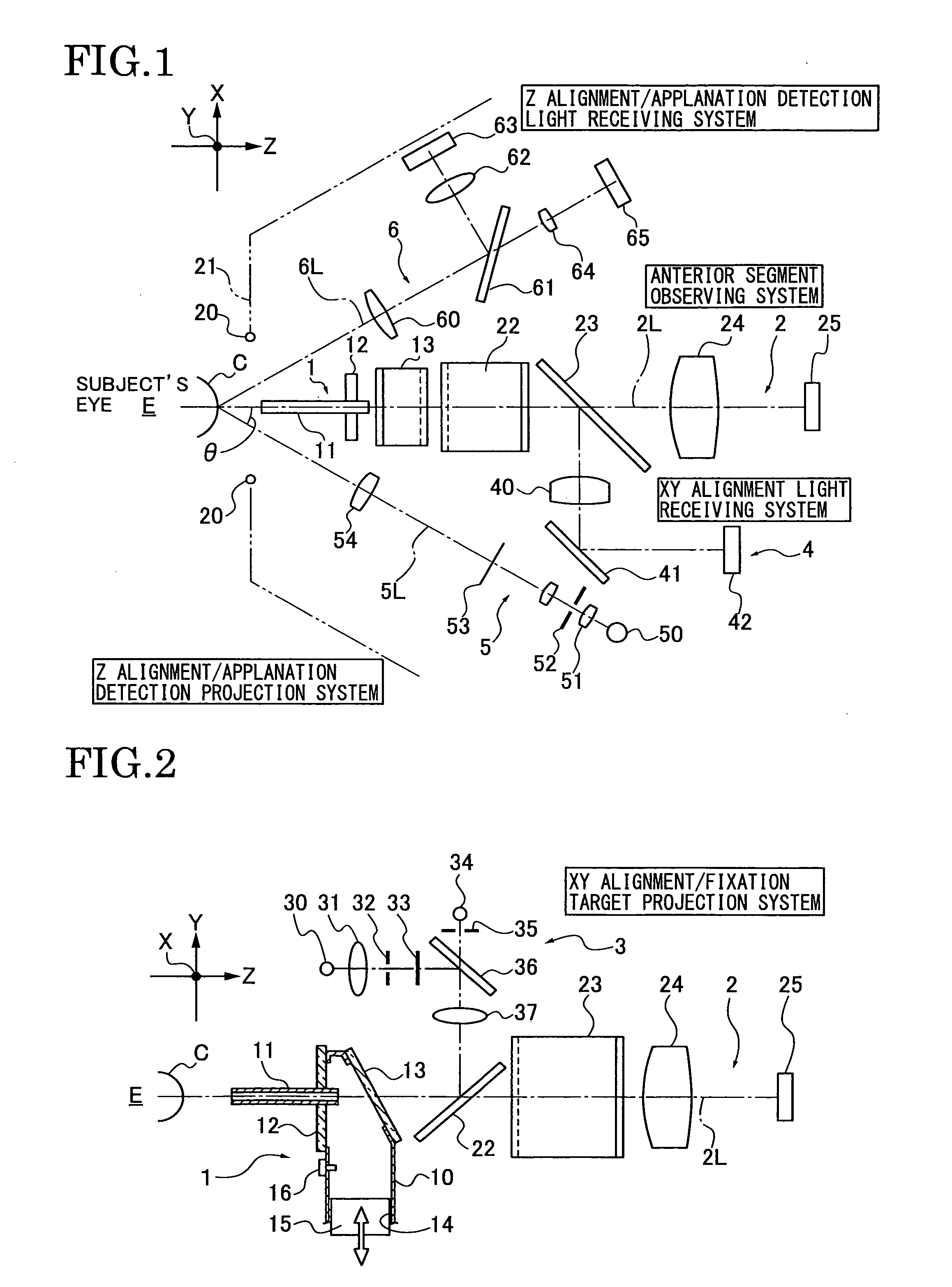
[0027]FIG. 1 is a plan arrangement view showing an optical system of a non-contact type tonometer of the first embodiment. FIG. 2 is a side arrangement view showing the optical system thereof.

[0028]The non-contact type tonometer of the first embodiment is configured to measure an intraocular pressure by deforming the cornea of a subject's eye E in a non-contact state. As shown in FIG. 1, this non-contact type to...


PUM


Abstract

A non-contact type tonometer includes a air injector for blowing air to a cornea of a subject's eye along a reference axis to deform the cornea, a projection optical system for projecting projection light onto the subject's eye, a light-receiving optical system for receiving reflected light which is projected from the projection optical system and reflected on the subject's eye, an alignment unit for positioning the projection optical system and the light-receiving optical system in the direction of the reference axis based on a light amount of the reflected light which is received by the light-receiving optical system and an intraocular pressure detector for detecting a deformation of the cornea based on the reflected light amount. The projection optical system includes a light flux shape regulator which regulates the projection light such that the projection light has a non-circular shape extending in a predetermined direction.

Description

CROSS REFERENCE TO RELATED APPLICATIONS[0001]The present application is based on and claims priority from Japanese Application Number 2007-195340, filed on Jul. 27, 2007, the disclosure of which is hereby incorporated by reference herein in its entirety.BACKGROUND OF THE INVENTION[0002]1. Field of the Invention[0003]The present invention relates to a non-contact type tonometer which blows air on a cornea of a subject's eye and detects a state of a deformation of the cornea of the subject's eye to measure an intraocular pressure value of the subject's eye.[0004]2. Description of the Related Art[0005]Heretofore, various non-contact type tonometers (also referred to as “non-contact tonometer”) have been known. Such a tonometer blows air onto a cornea of a subject's eye with a nozzle to applanate the cornea, and measures an intraocular pressure value of the subject's eye on the basis of an internal pressure of a chamber when the cornea is deformed into a certain shape.[0006]Of such non-...

Claims


Application Information

Patent Timeline
Patent Type & Authority Applications(United States)
IPC IPC(8): A61B3/16
CPCA61B3/165
Inventor NAITO, TOMOKOYANAGI, EIICHISAGEHASHI, HIDEO
Owner KK TOPCON
Why Eureka
Try Eureka